I wanted to try an ortholinear keyboard but was worried that the reduced layout of the plank/preonic, along with the modified layout, would be too frustrating. There are some cheaper XD75 kits on Ali Express but they're still not really cheap; and if you're outlaying any money, do you want the cheapest or do you want something decent? Should you get the cheapest switches or best switches, super basic caps or ones you actually like, which ones do you actually like??? This is part of the reason that I like shopping second hand, it reduces the available decisions. There are no second hand ortho keyboards though :-(. I guess the issue boiled down to the fact that there was no real budget option, and I wasn't sure that I wanted to outlay the amount required to get a good one, when I wasn't sure I even wanted one.
I'd already been trying out some second hand traditional layout mechanical keyboards and had found that you could get some really decent models quite cheap. This made me wonder whether I could use a second hand donor keyboard for all parts and just use a new ortho frame. This idea grew on me the more I thought about it; there was also a cheap bent stainless frame on Ali, which is a style I particularly liked. My main concerns with this idea were using keycaps in different positions than they suited (I'd only be able to use the one unit keys from the donor board), and being able to desolder the switches succsessfully. I thought it was worth looking into so I started looking for second hand donor keyboards that would suit.
A surprising amount of Razer Chroma keyboards were coming up cheap ($40AUD). These boards have a column of 5 macro keys, which means 5 more keycaps and 5 more switches, Win! Around this time I remembered that I had an Arduino Micro hidden in my cupboard somewhere, so that was another cost saved/something I could upcycle. Things were looking pretty good for the concept and after reading that the Razer green switches were essentially copies of Cherry Blues, my mind was made up. I searched and looked at one Chroma before I settled on the most basic model (I think) which I was fairly sure would have the clicky switches (the one I checked first was a "stealth" model I believe). I bought a decent looking donor on eBay and once it arrived, the build began!
The build is documented with pictures below. I've added comments to explain what's going on in places.
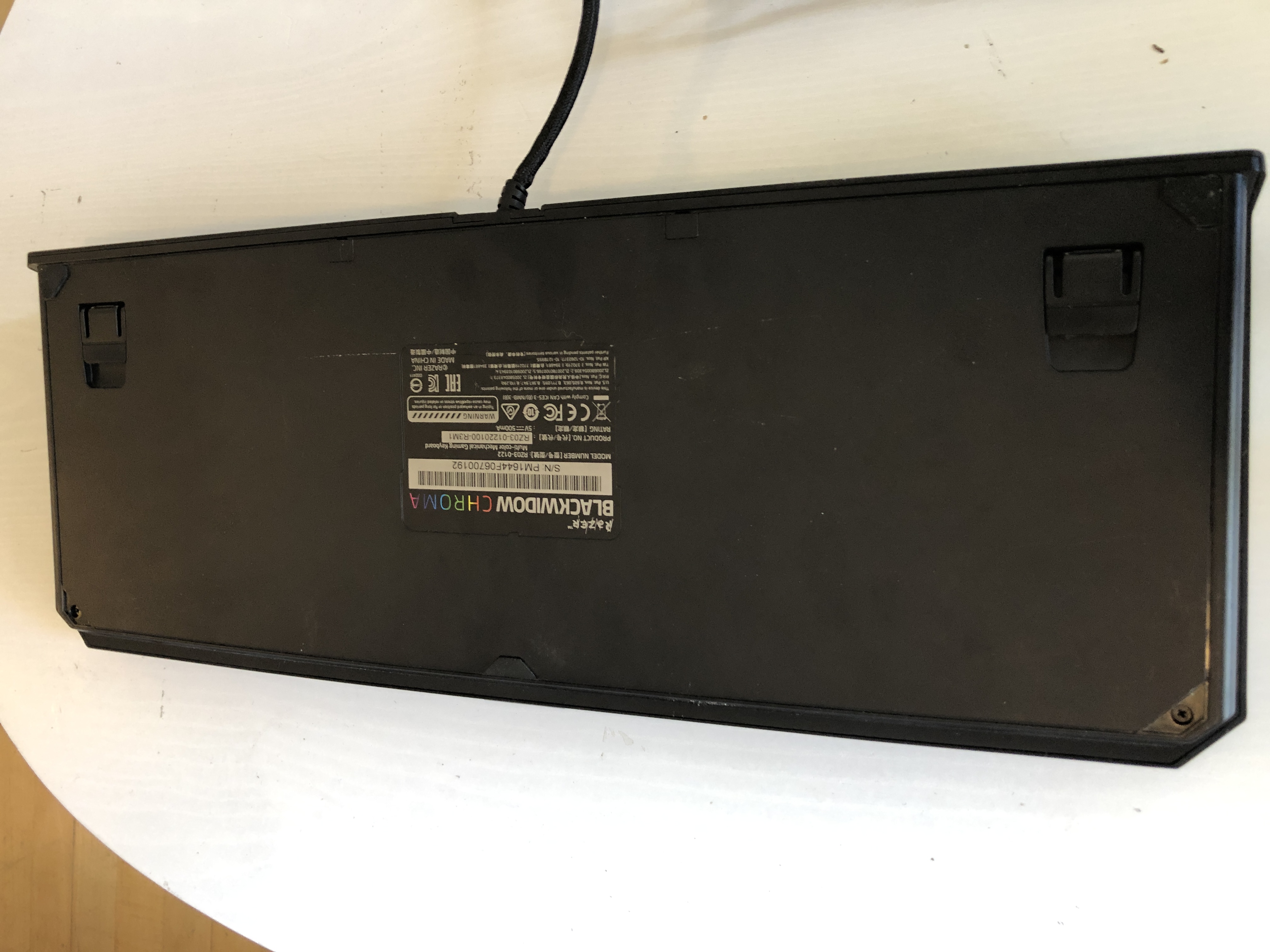
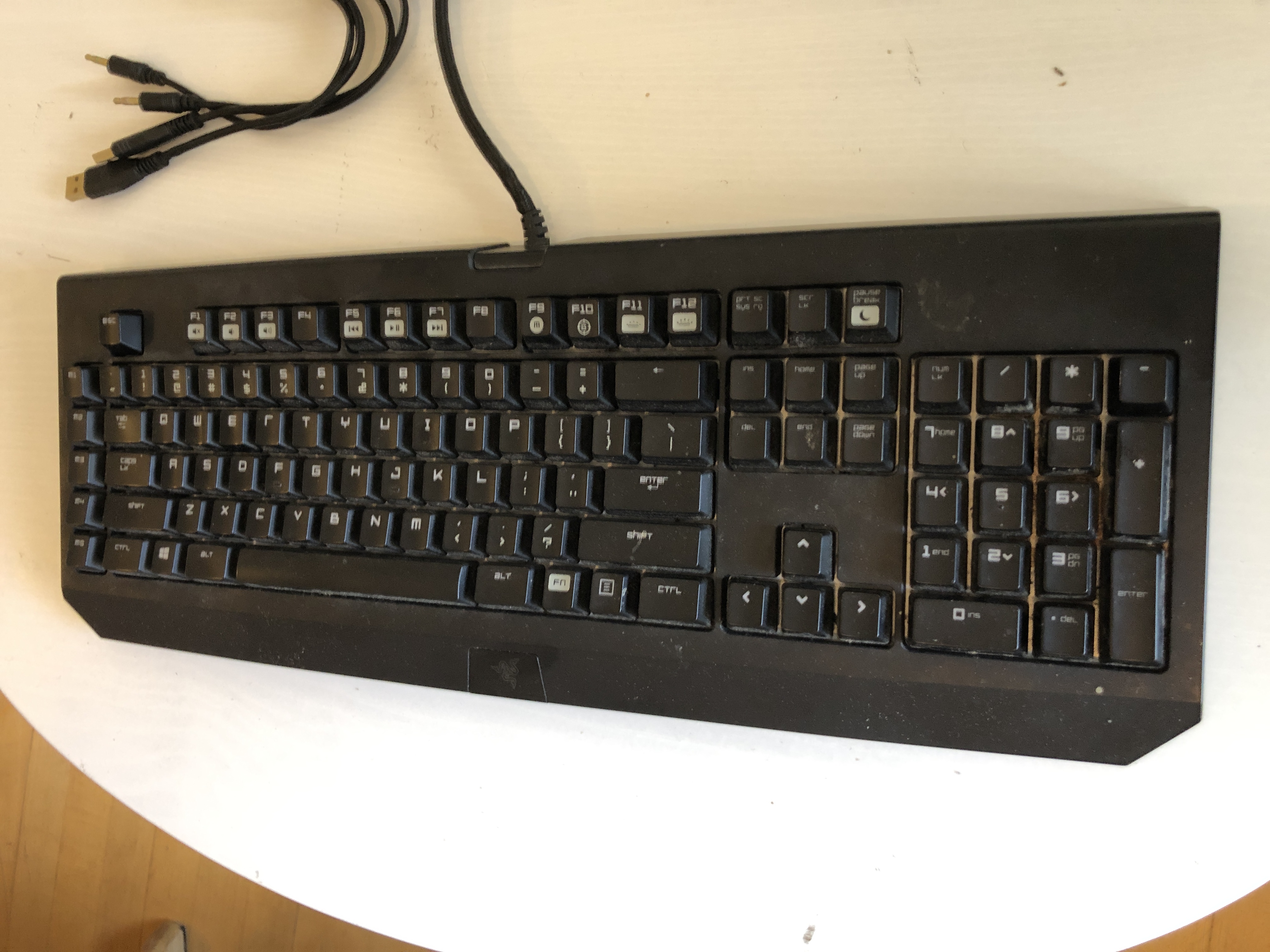
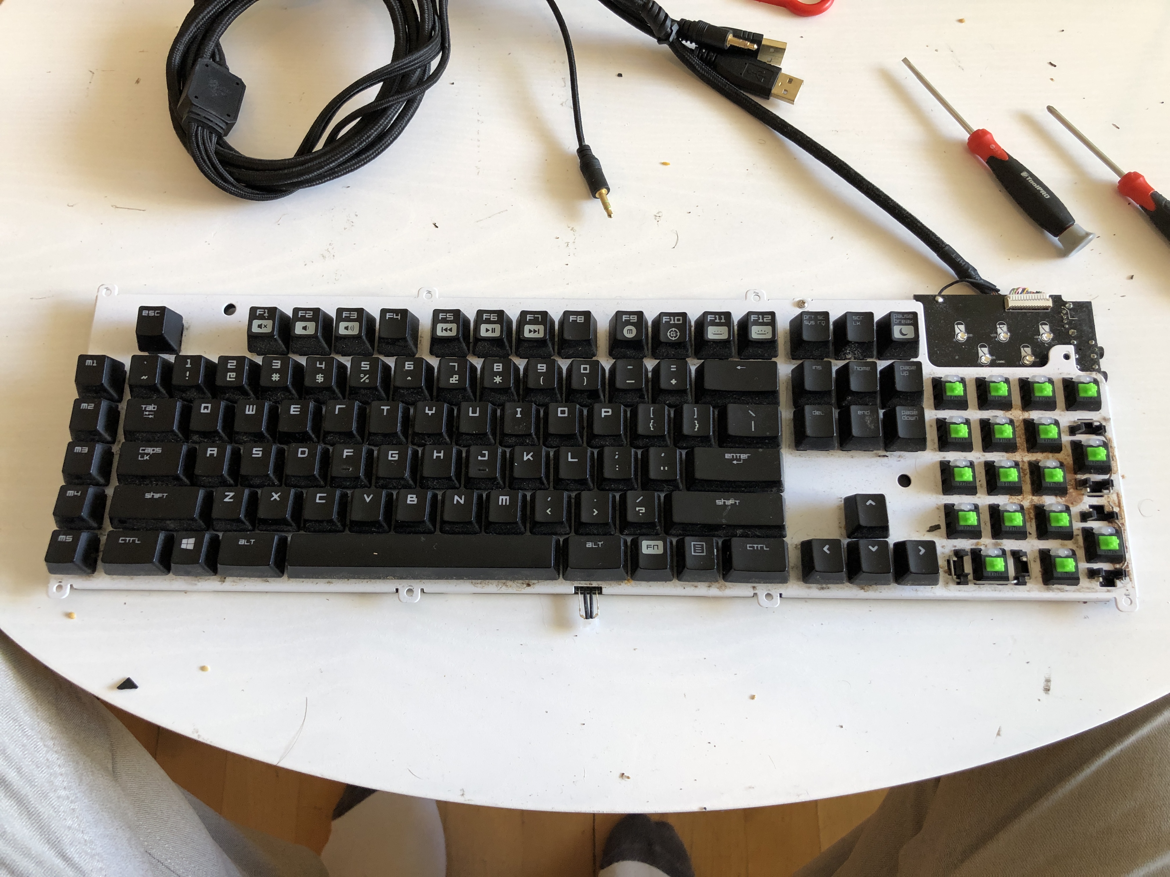
This the donor keyboard I got, looks pretty good but if you look closely there is nice coffee spill on the numpad... Also, some of the switches weren't clicky. This was quite dissapointing but I figured that I had enough to be able to get a full set that still clicked properly. I looked up this issue online and it's a common one, no simple fix either unfortunately.
Locations of the screws to remove the covers.
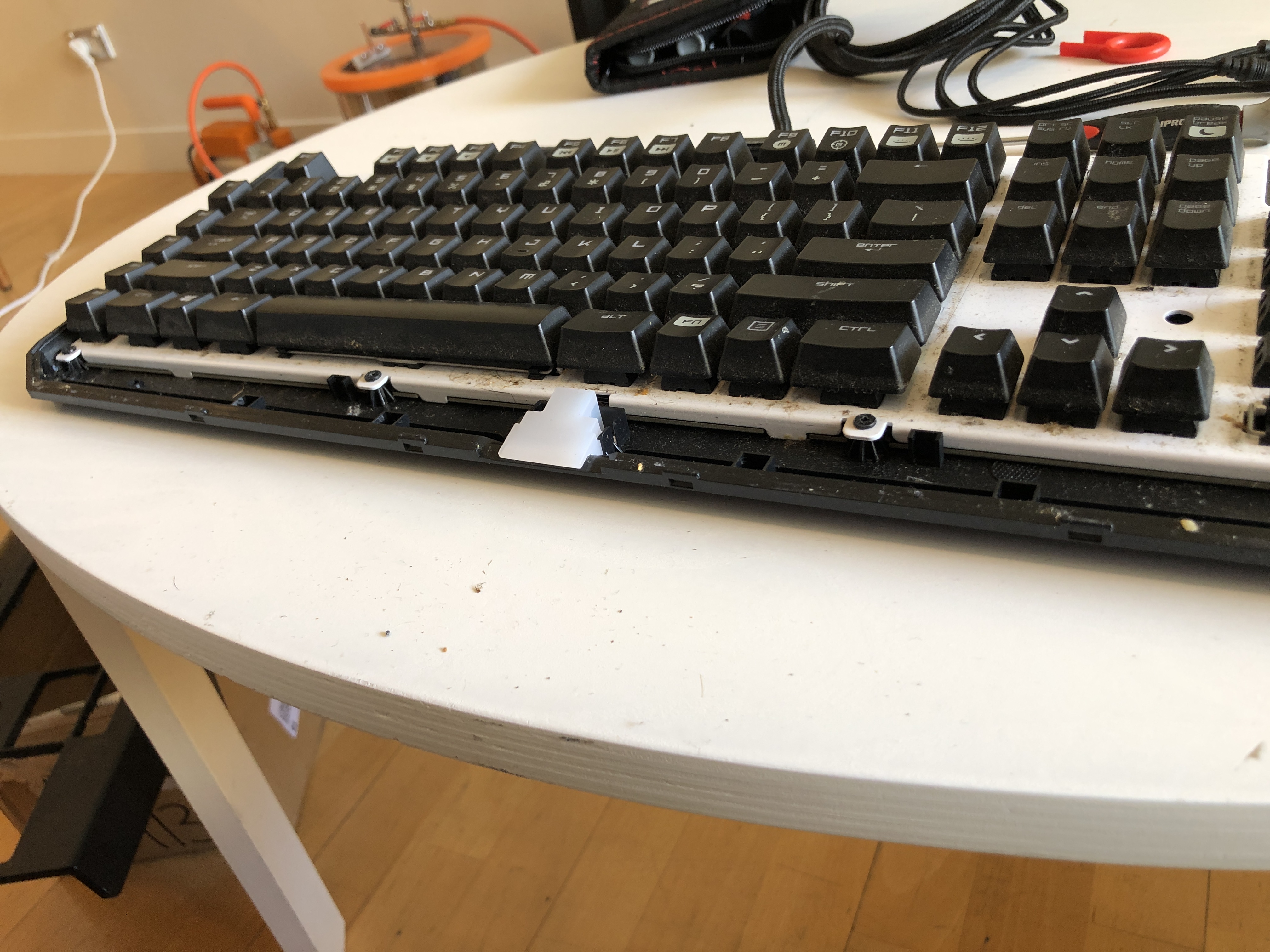
The numpad keycaps removed, just a matter of pulling them off. Coffee stain revealed.
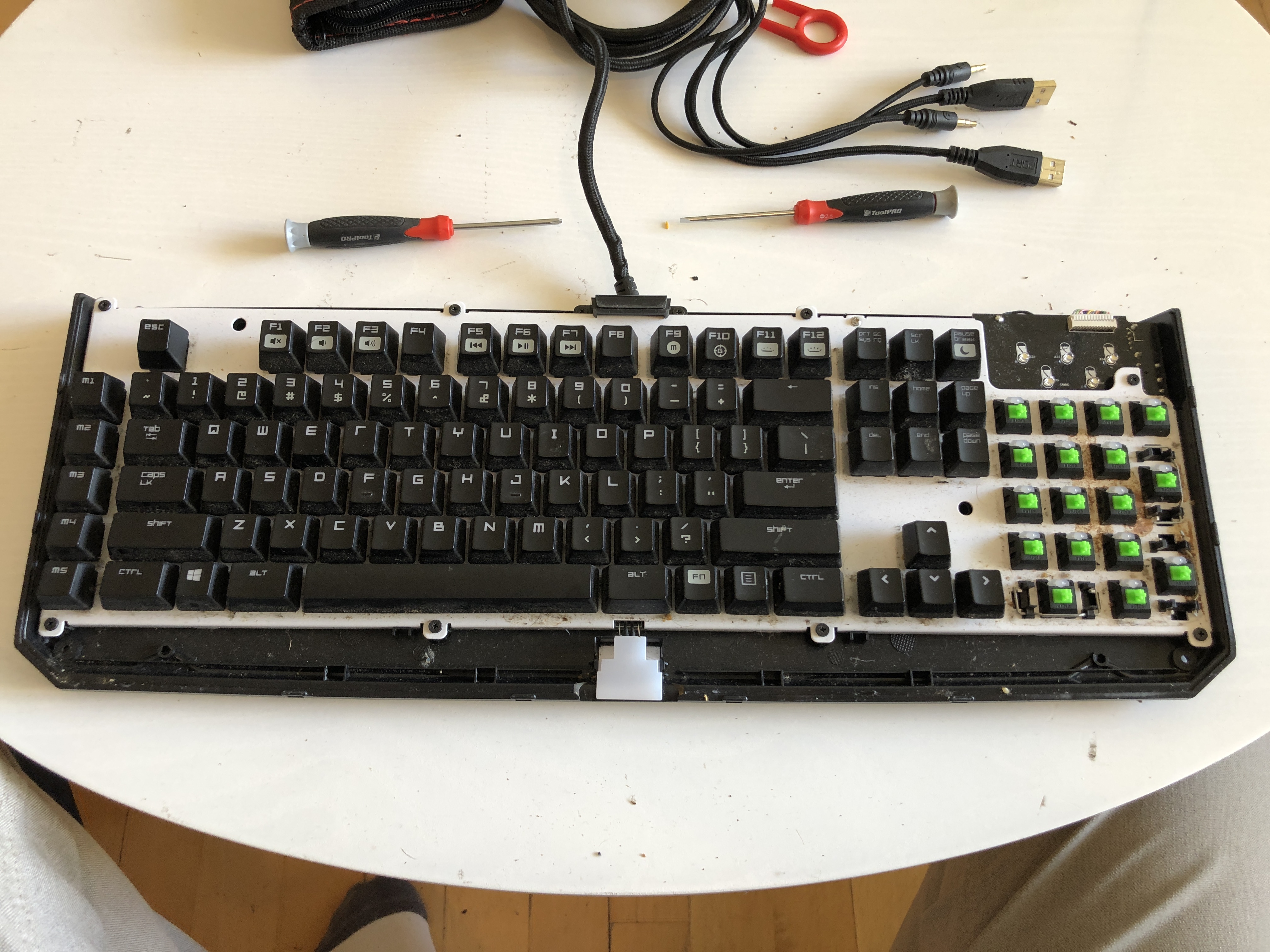
Top cover removed.
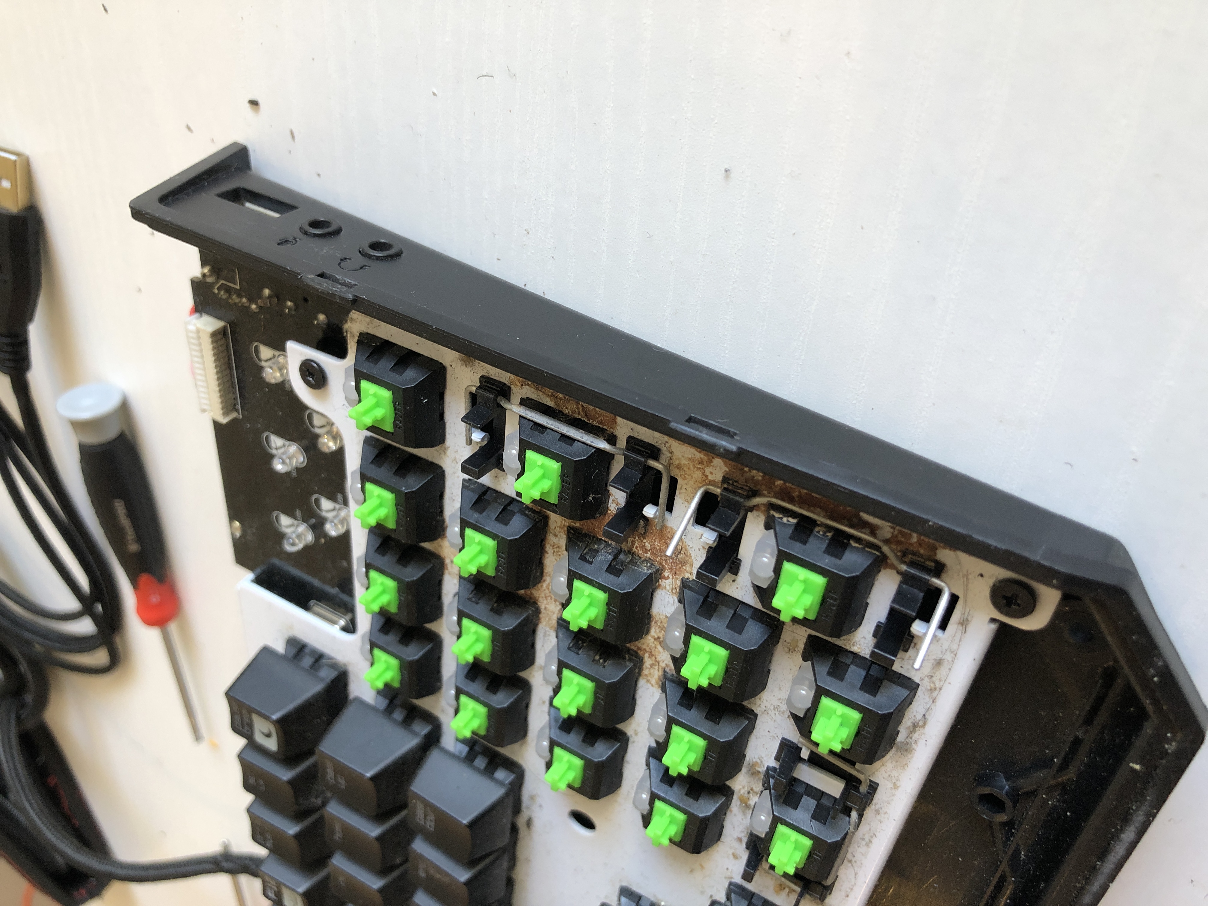
Clip positions, need to spread the top case in these locations to remove it.
Some more clip slot things.
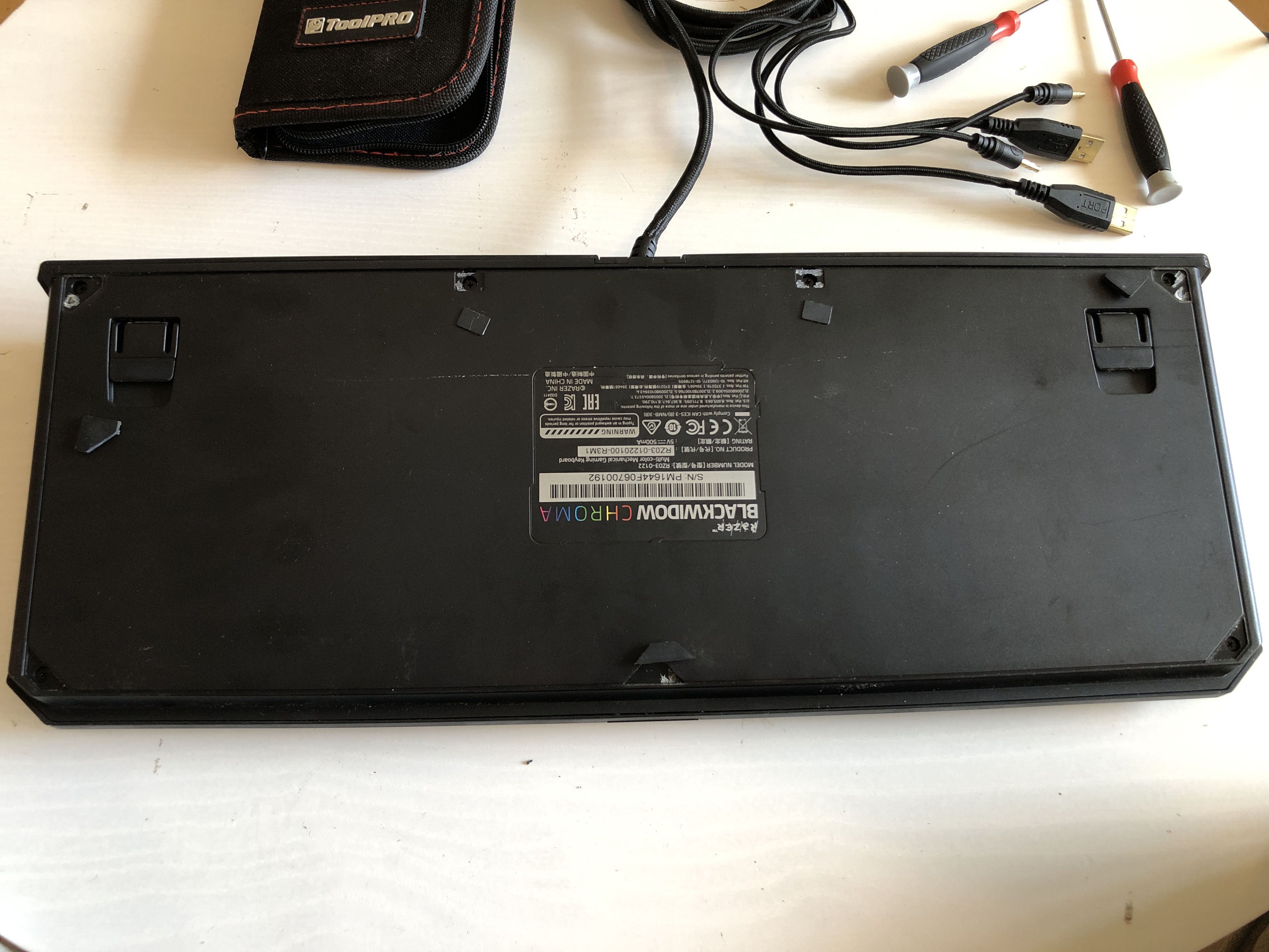
Bottom cover removed.
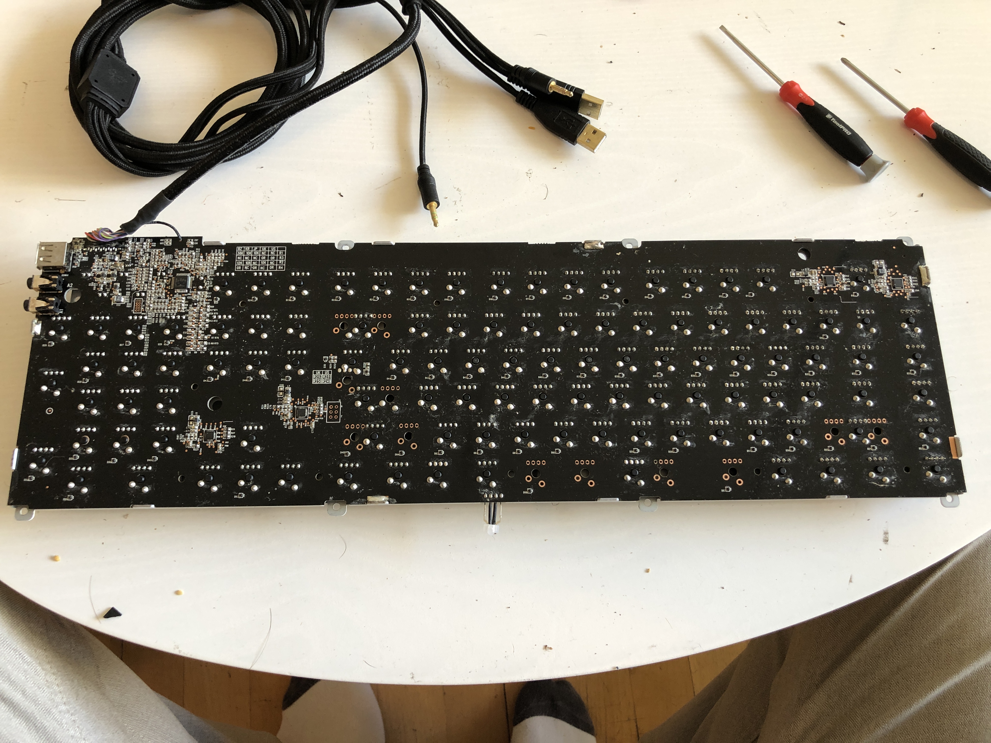
Back of the PCB, the wires need to be unplugged and a ground/shield wire desoldered to remove them.
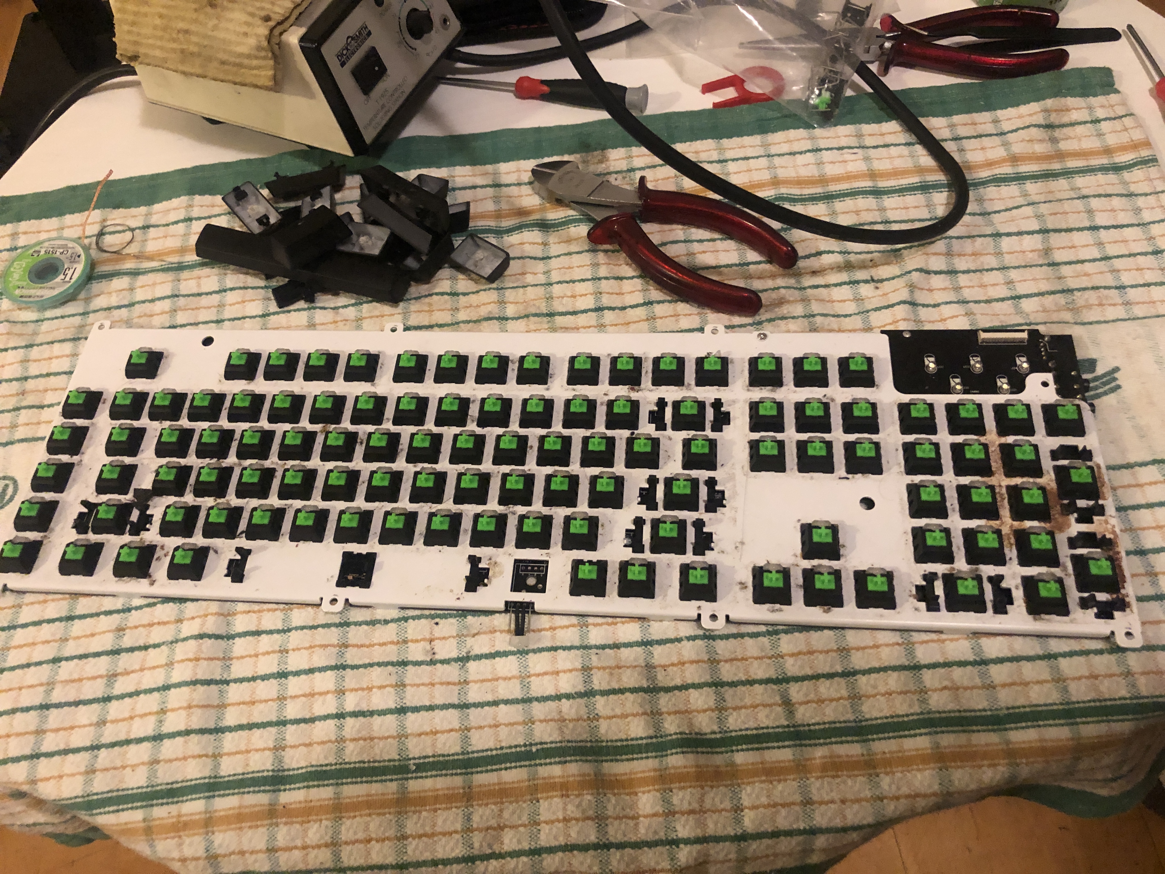
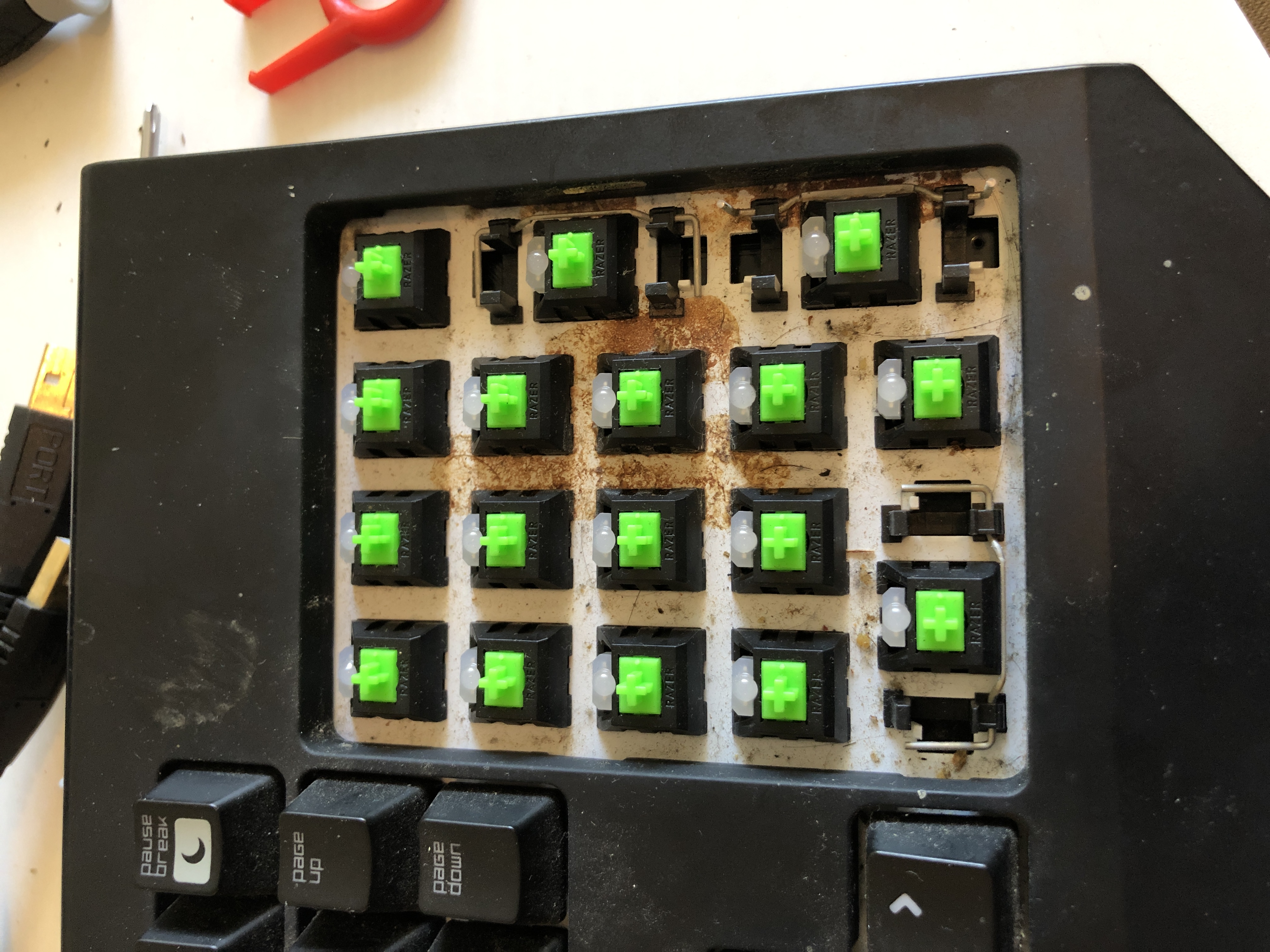
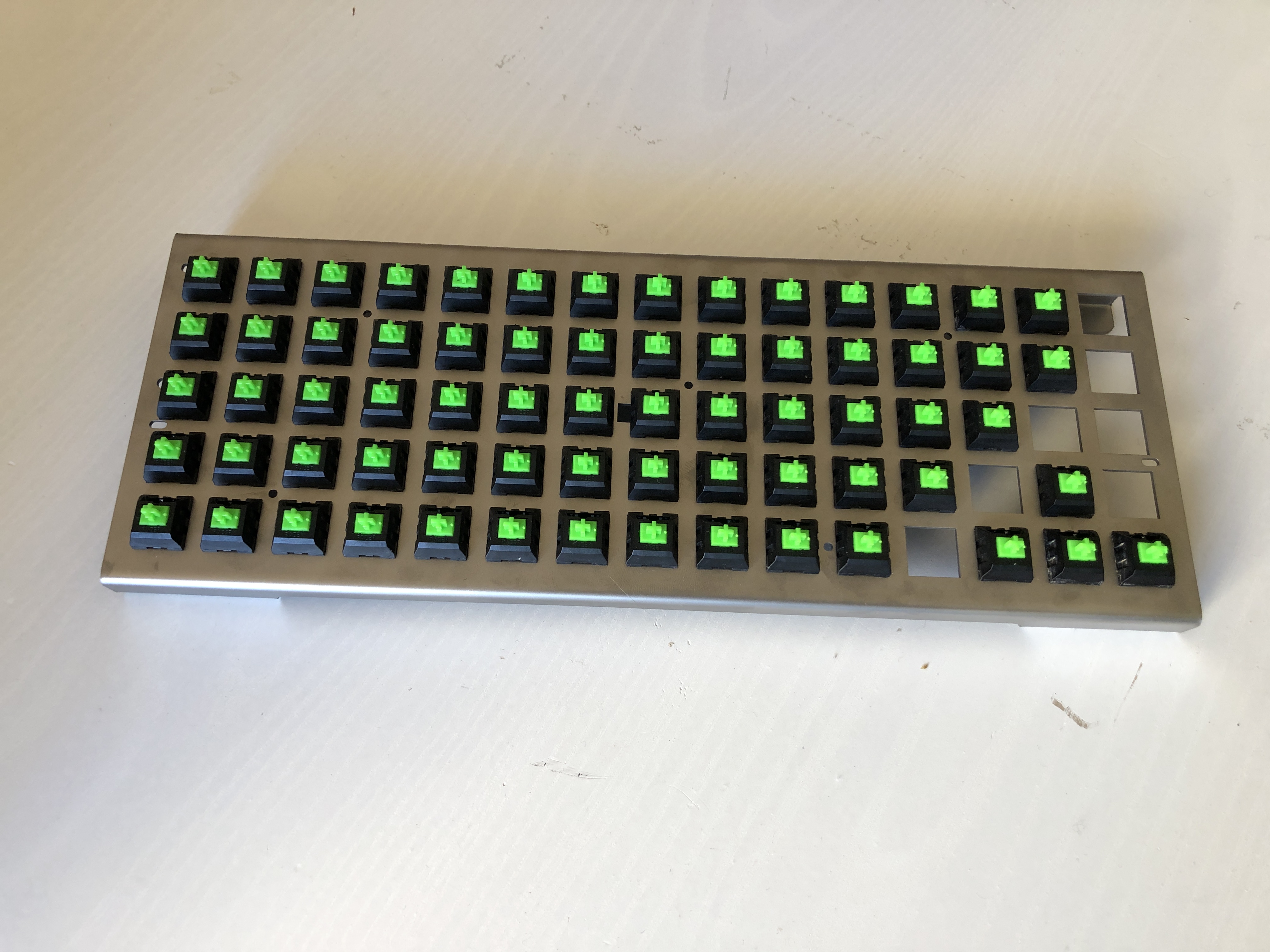
Time to start desoldering switches. Most of them have LEDs with 4 wires which actually go through the switch case. This wasn't looking straight forward. Two of the switches didn't have LEDs, space bar and fn, so I decided to start here. The difficulty in removing the switch is that the case is clipped into the metal front plate, and the pins are soldered. You need to melt the solder, depress the switch clips and pull the switch away from the PCB at the same time, with only two hands... In my first attempt at this I broke one of the pins off the space bar switch. I managed to get the fn switch out but it was painfully slow and the pins were getting very hot due to continuously heating and eeking them out. At this stage I thought the idea might be no good; I had to remove over 100 of these things, at a 50% failure rate, and I had no idea how to tackle the LEDs, on top of the above difficulties.
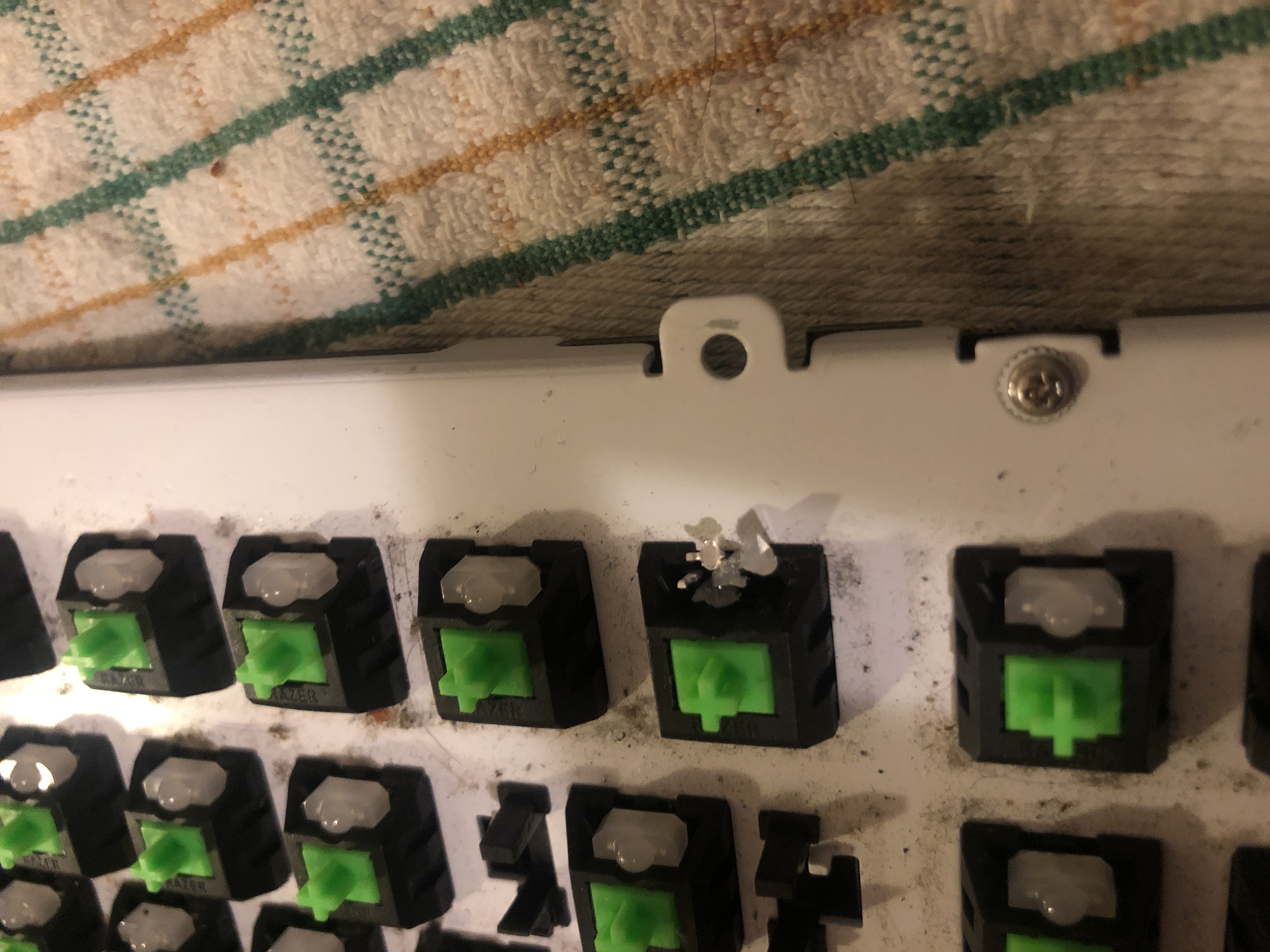
I slept on it and the next day had the realisation that I could destroy the LEDs to remove them. I got some side cutters and made three cuts vertically through the plastic casing, they split quite neatly into 4 parts. I was then able to desolder them individually. With that issue solved I decided to start carefully refining my technique to remove the switches.
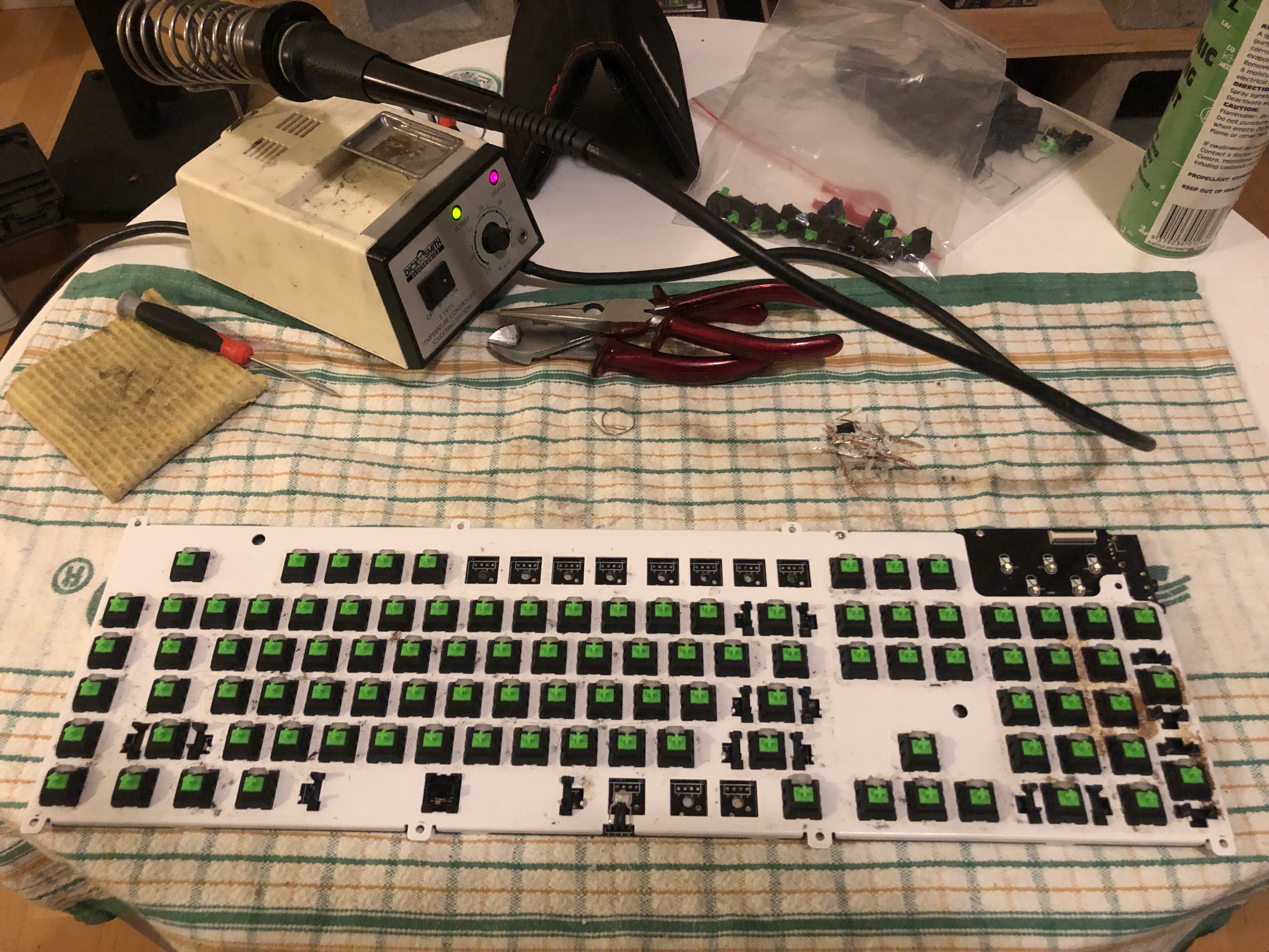
I ended up developing a decent technique to remove the switches, I'll try to describe the steps involved here. I should note that I tried to use solder wick but wasn't succesfull. I am by no means a pro with the soldering iron so maybe someone else would have more luck, or maybe there is a better tool. Either way, what I did was:
Once I got going with this method, it took about 2 minutes per switch to remove. As a bonus, either the heat, or the general trauma of removing the switches, or both, was restoring their clickiness! I'm not sure why this would help, my current theory is that the standard lube slowly melts down to the bottom of the switch case after a while and damps the cage thing as it clicks down. Having them upside down and heating them causes the lube to move back to the top, restoring the click.
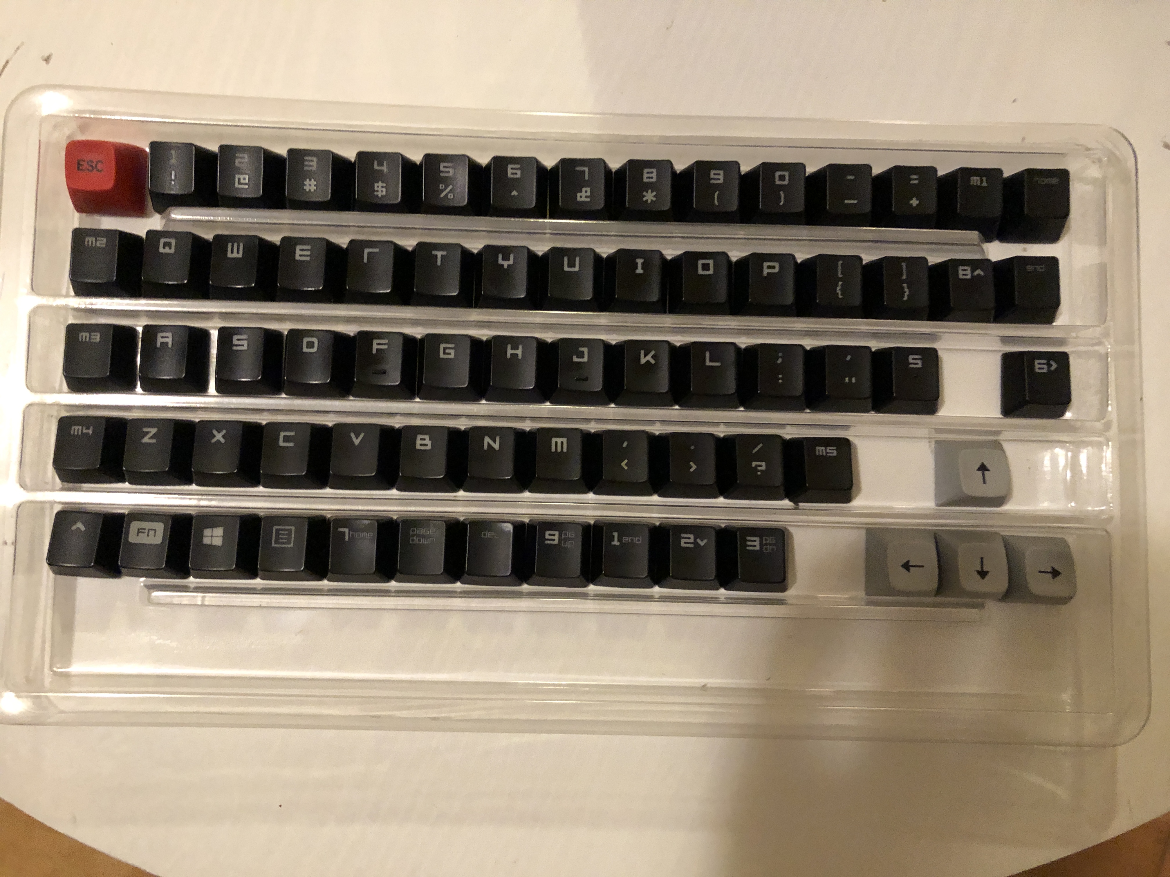
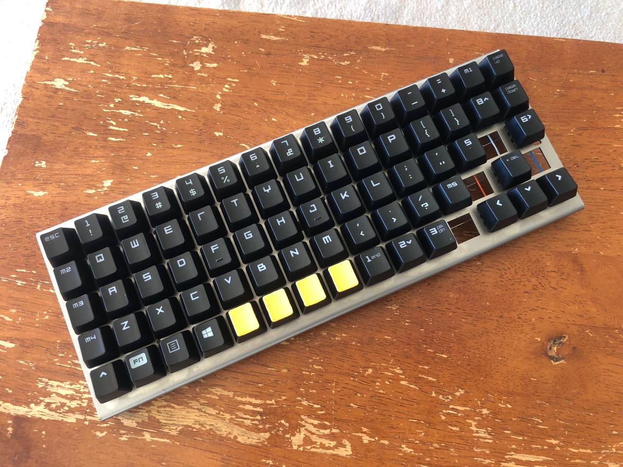
In between removing switches, I experimented with what keys to use in what position. I also had a key set that a good mate gave me so I tried some of those in some places to add some colour (the set was too small to use entirely)
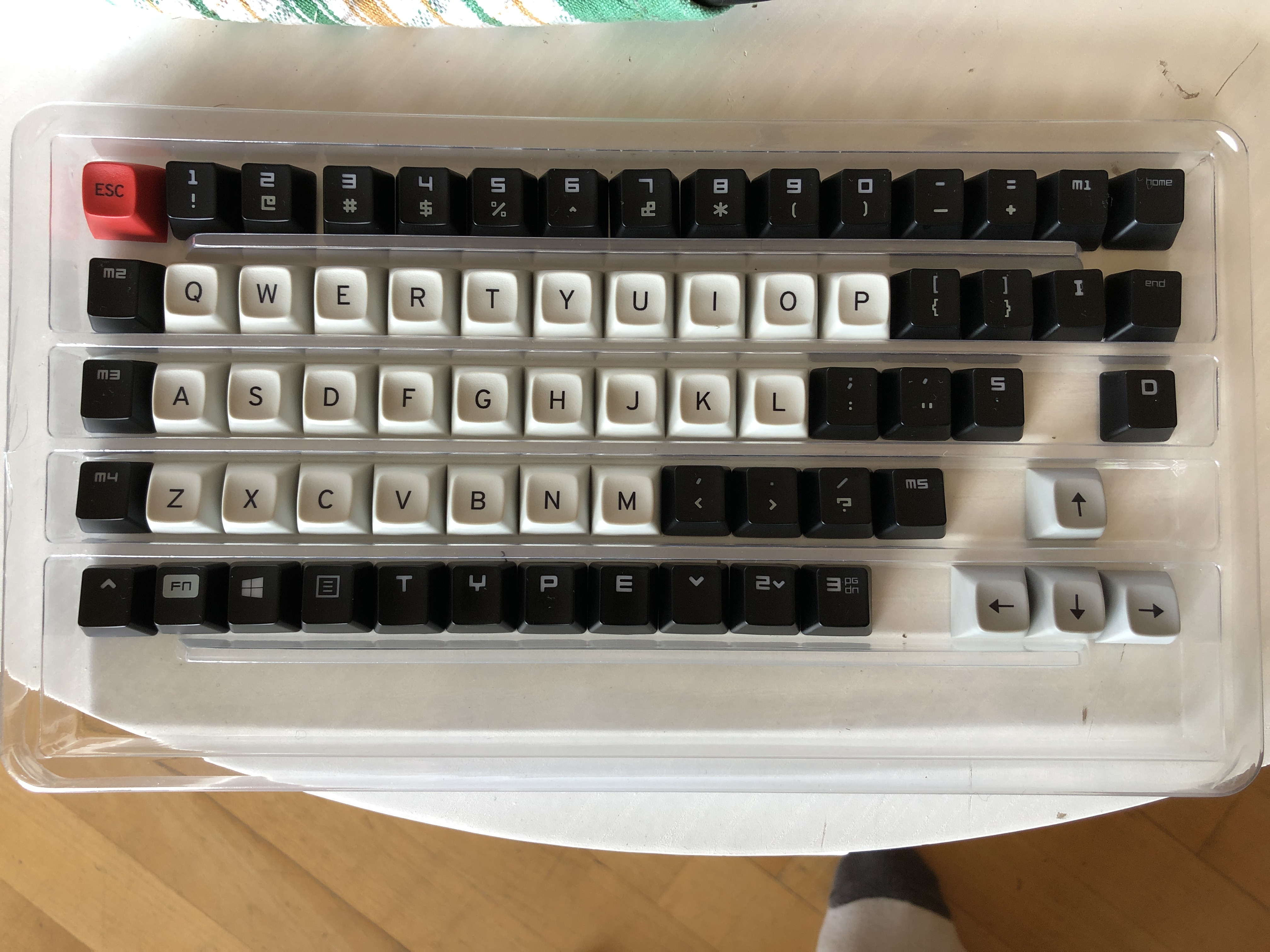
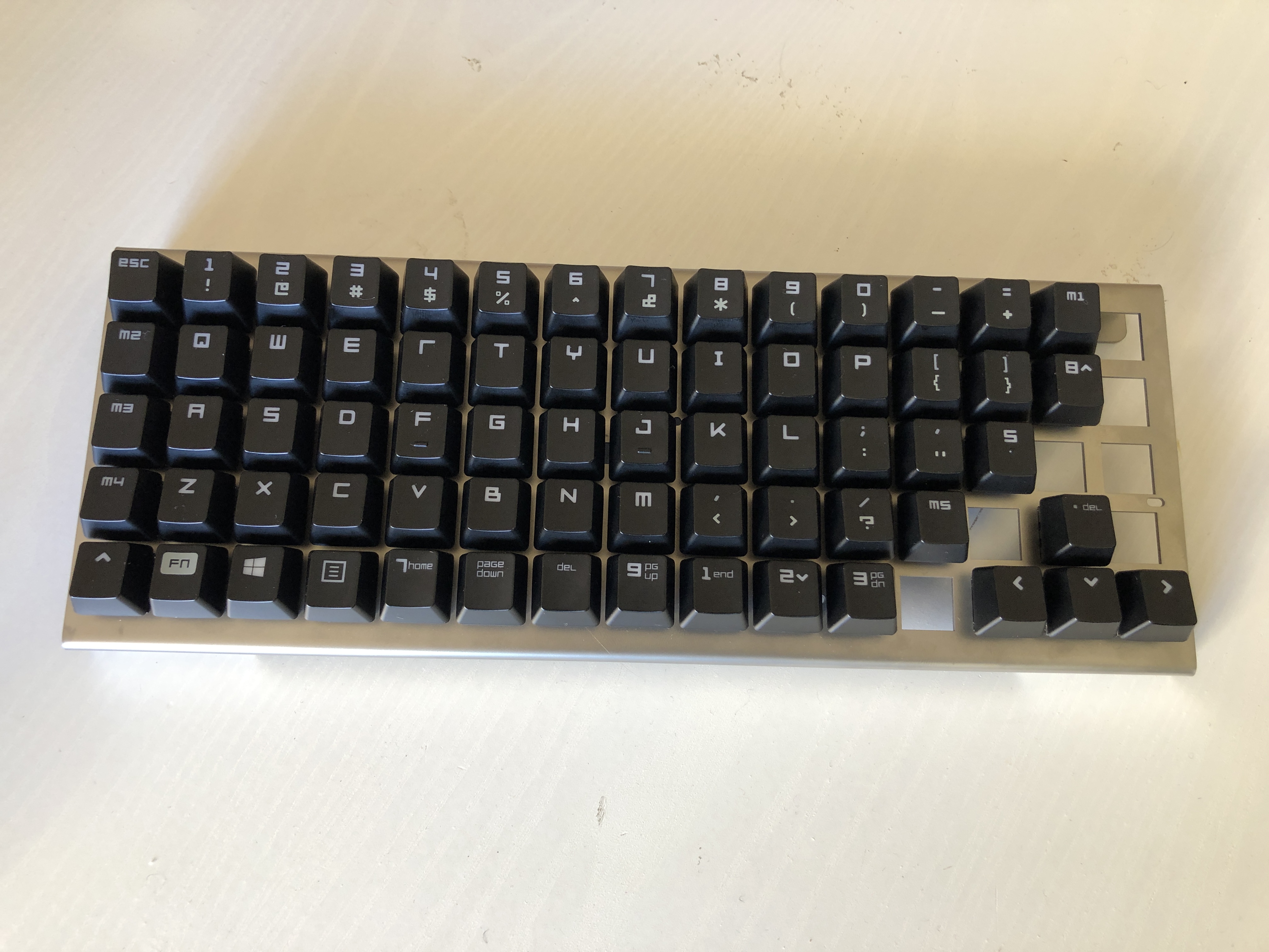
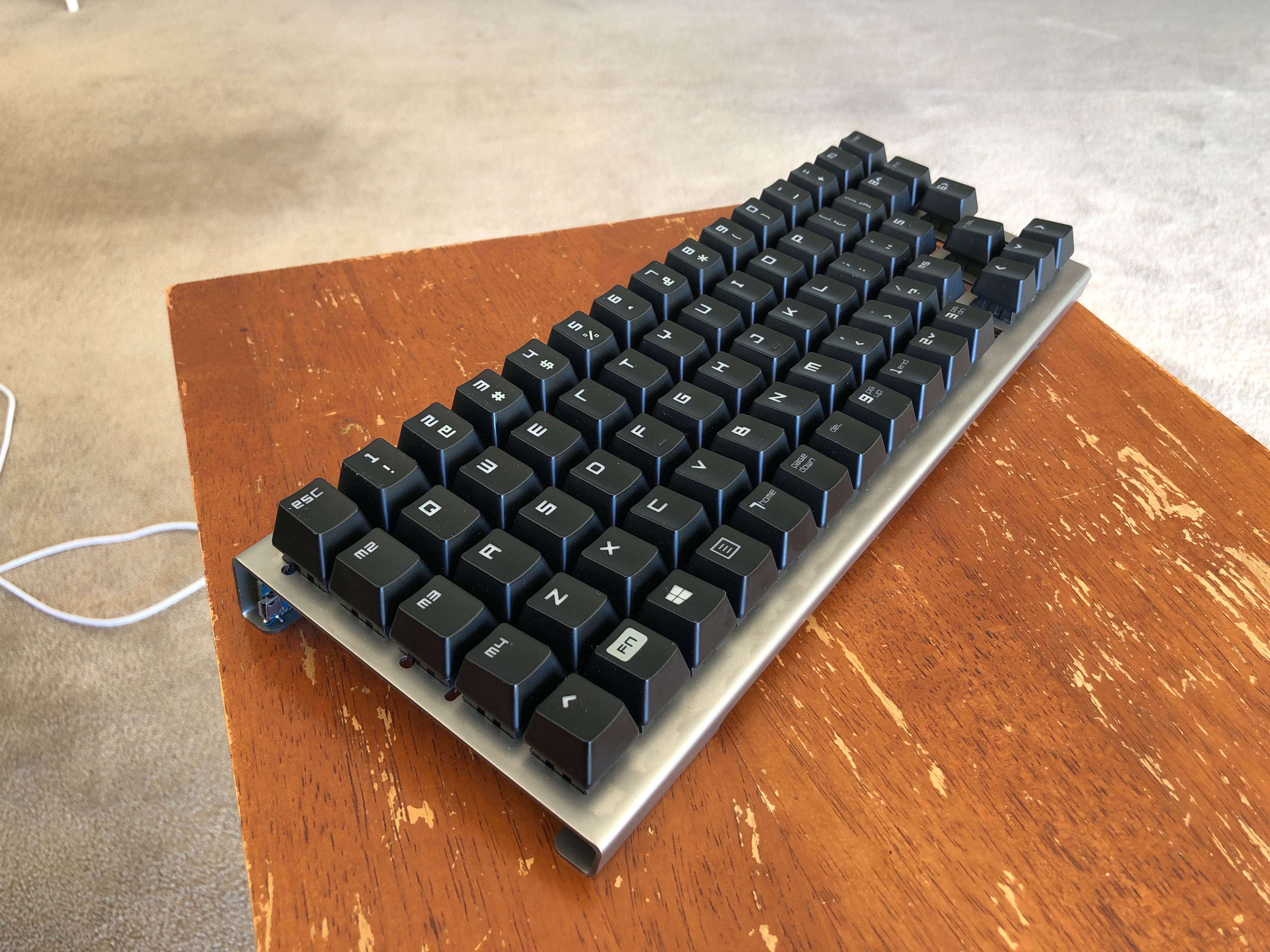
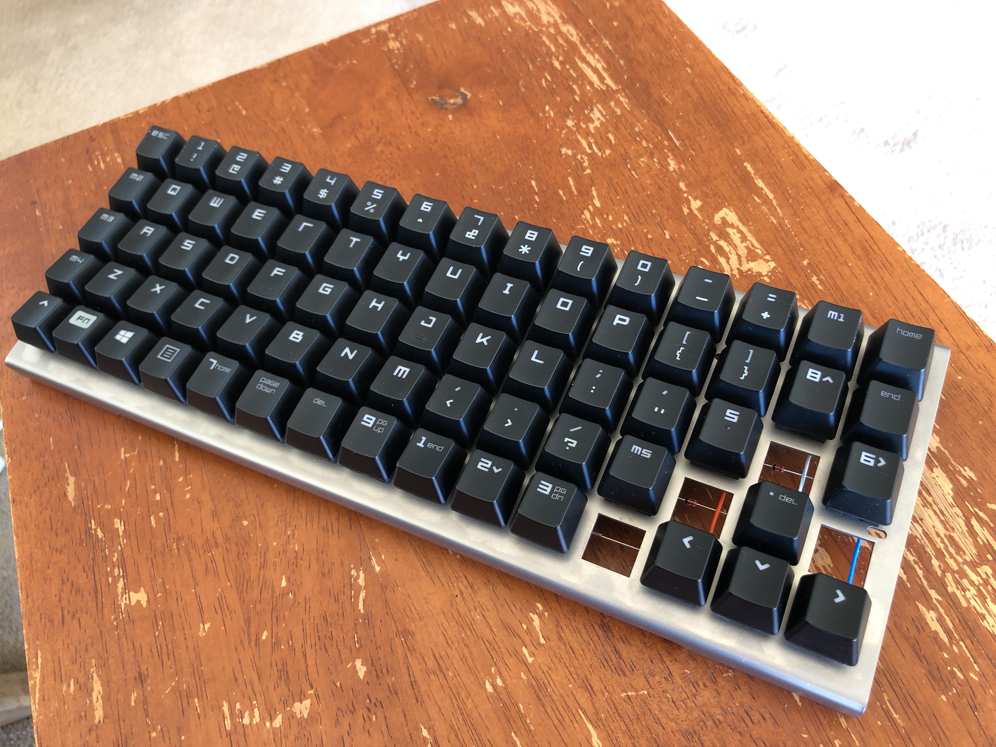
Amazingly, there is almost the exact amount of key caps on the Razer Chroma to populate a ten-key-less type layout on the XD75 frame. There are stacks of spare top row keys, because of the F keys, but there are only three keys extra from the rest. I used two on the right hand side to implement pg up/down and del. All rows even have the correct profile except the bottom, where I used 4 keys from the second-from-the-top row as space bar keys.
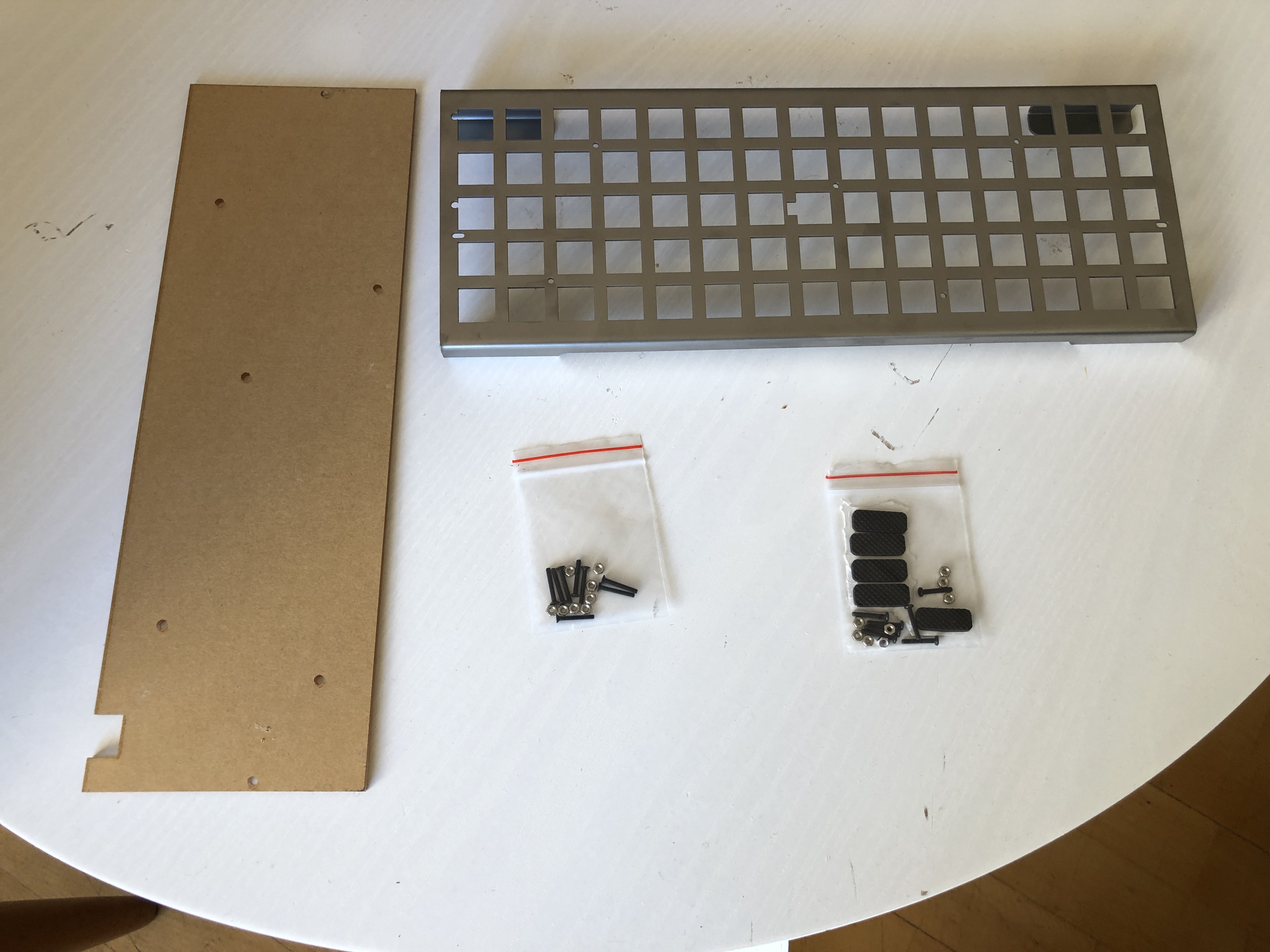
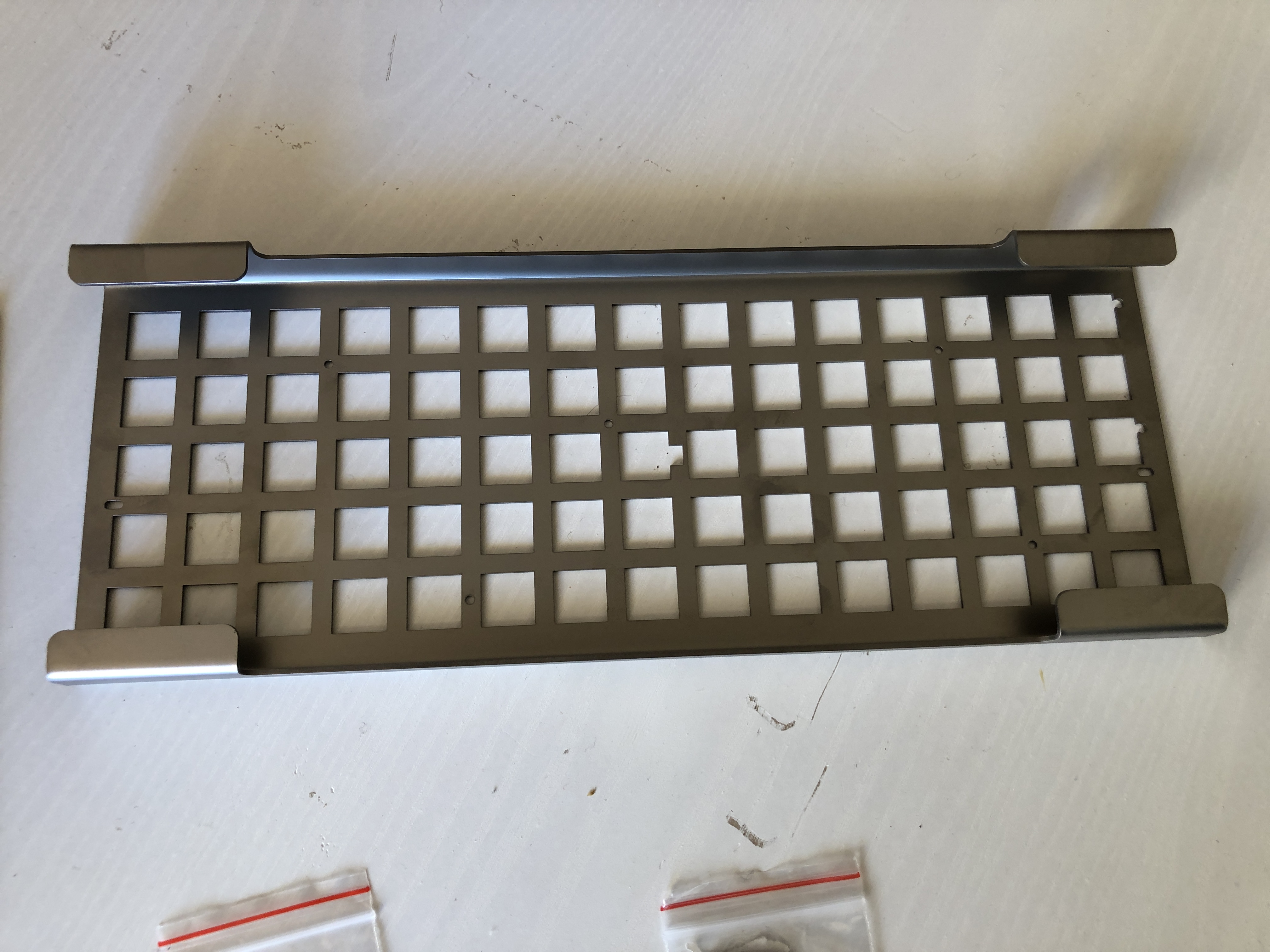
XD75 frame arrived, really nicely done. I love the simplicity and the nice clean cuts.
It was around this time that I decided to call the keyboard the Locost. Locost is a name given to kit cars that are based on the Lotus 7 design but are home made copies hence, lo-cost. The method used to keep costs down with these home made cars, is to buy a complete donor car, make a smaller, lighter chassis, and then transplant all the useful parts from the donor. I felt that I was taking a large inefficient keyboard and using its parts to make a smaller, higher performance keyboard :-P I'm also into Lotuses.
Tried some of the other key caps but I didn't like the grey against the stainless. Also the keyboard is made of so much scrap that it seemed wrong to use new key caps on it.
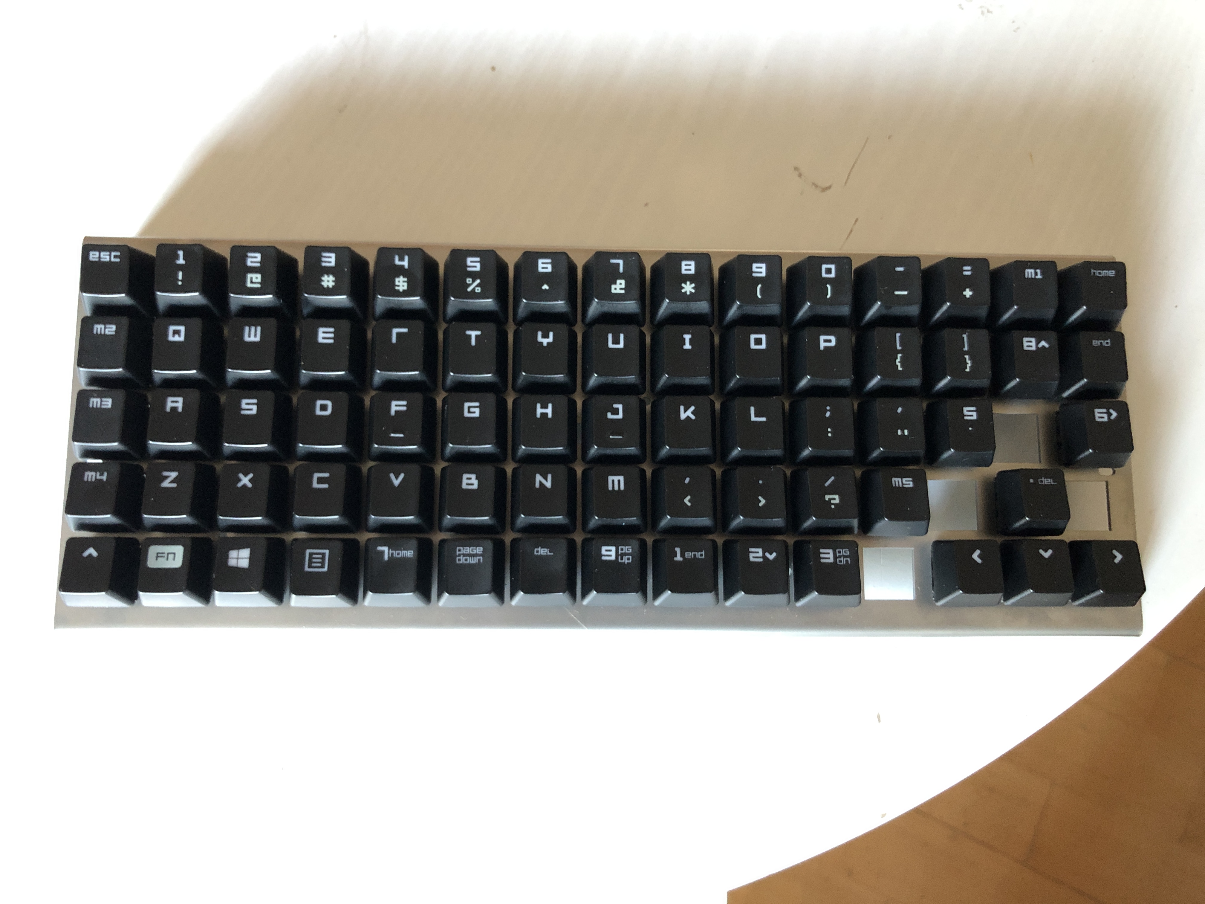
This is the layout I settled on. Really happy with all the key locations. It's pretty easy to work out what they all do except the space keys, but they are differentiated by their profile.
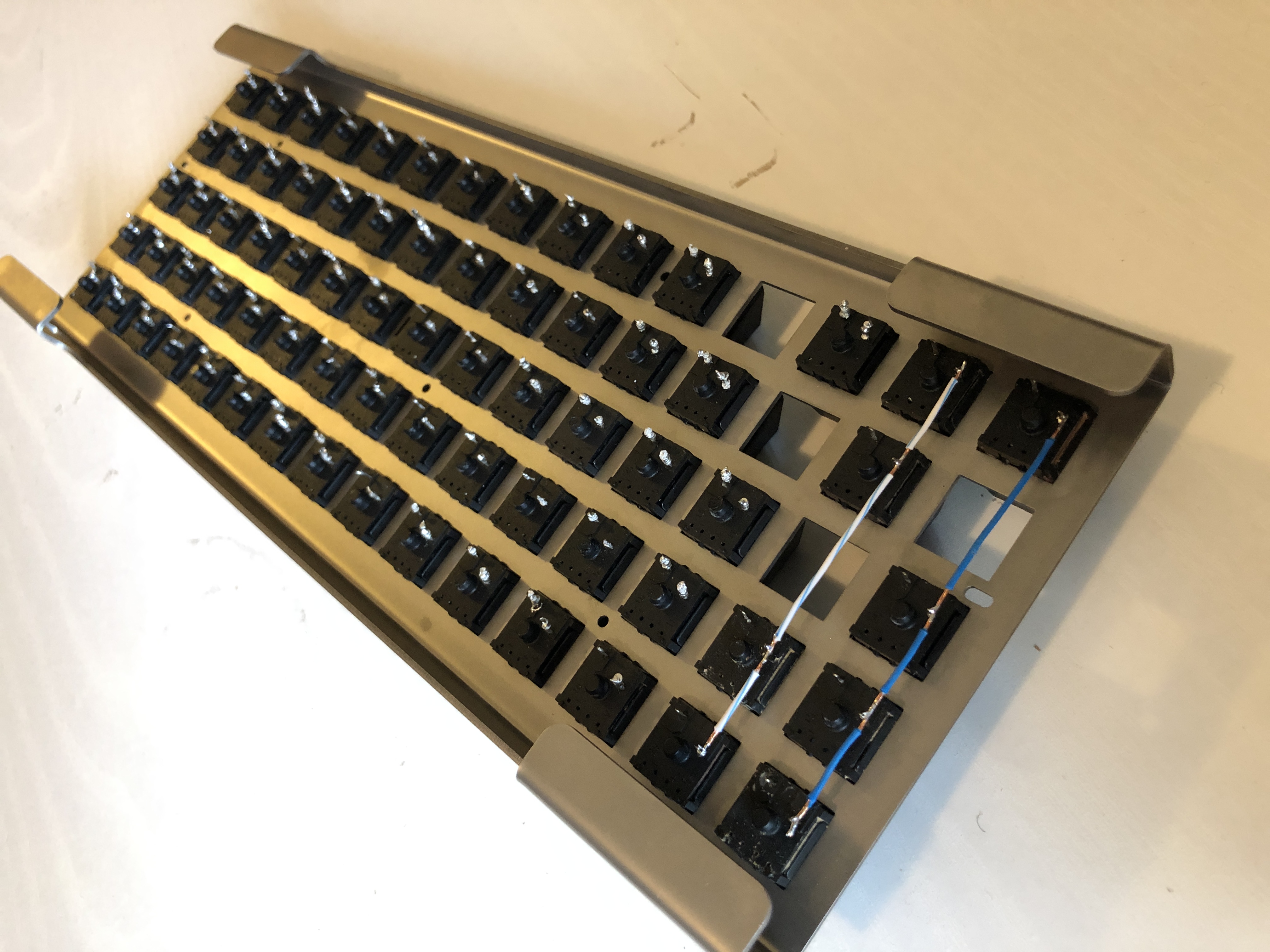
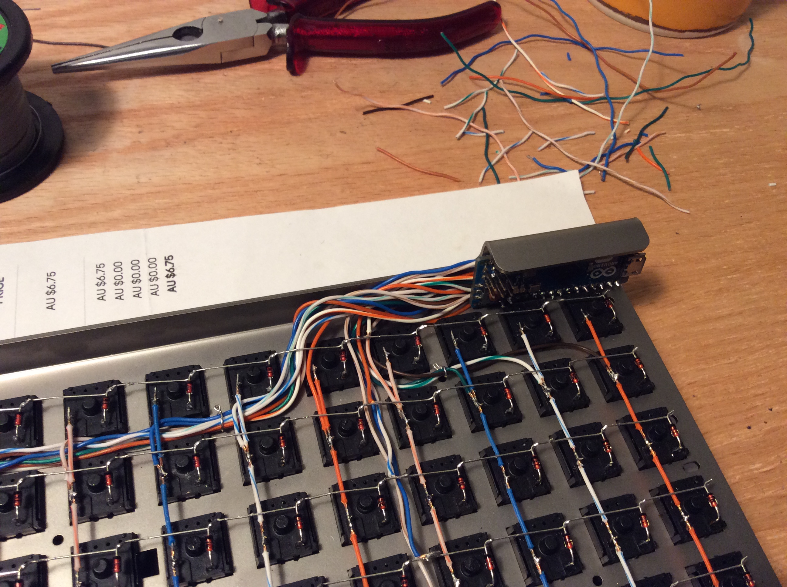
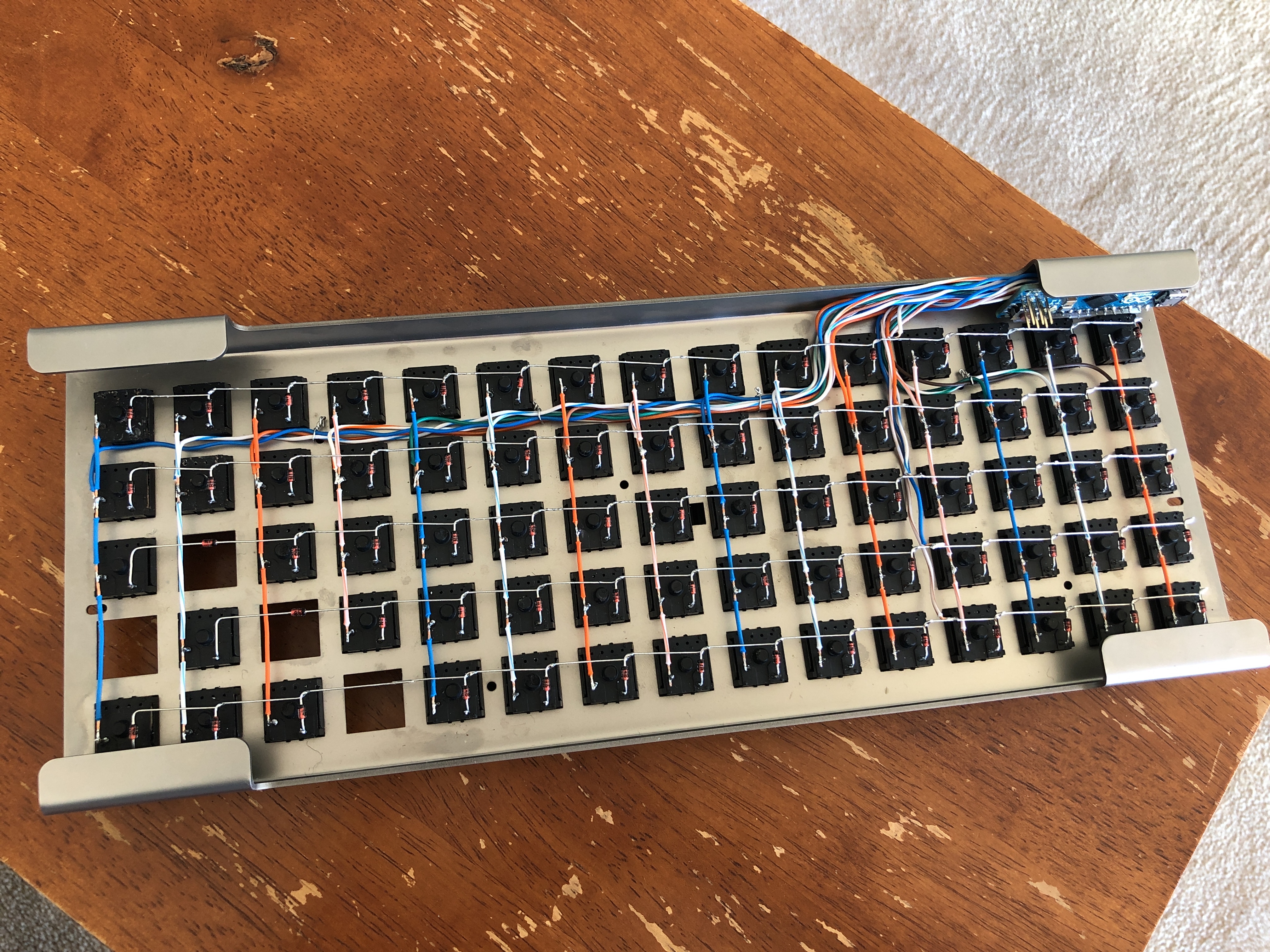
Next was to solder the column wires. I had an old ethernet cable that I had already used for another project. It had enough wire left on it to do all the column wires. I cleaned up the switch pins with some solder wick. My GF advised me to use just blue and orange to make it look better, I've never had an eye for such things. I think she was right, though green and brown would have looked pretty cool too I think.
The insulation can be removed from the middle sections by cutting a ring around, and then sliding the whole lot along.
Column wires done, there was a bit of a pause in progress after this while I moved house.
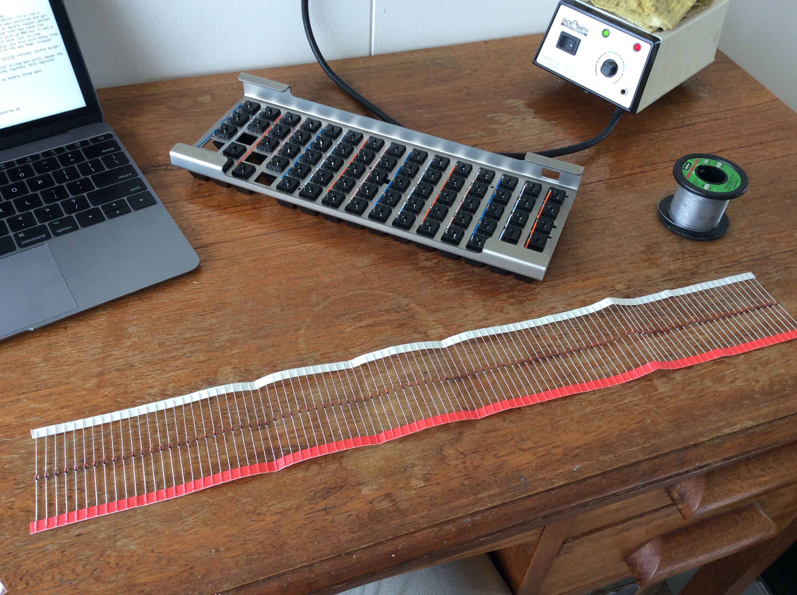
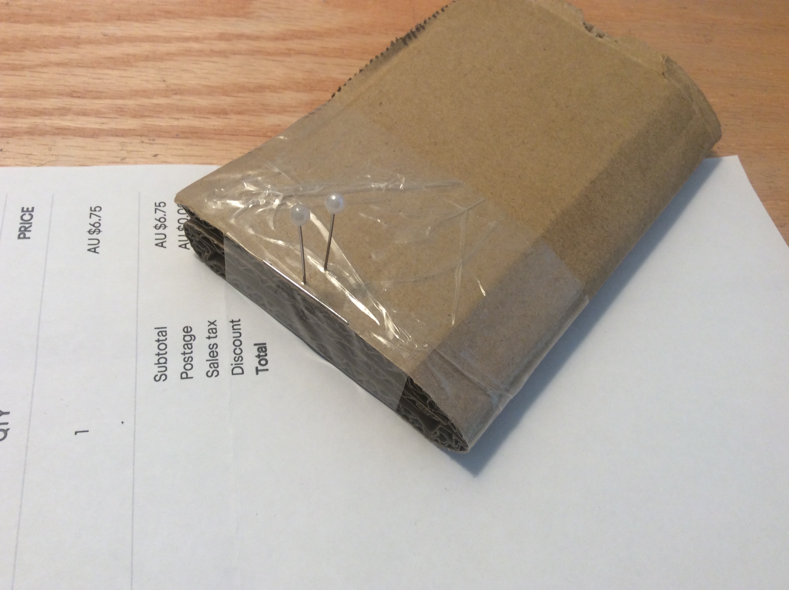
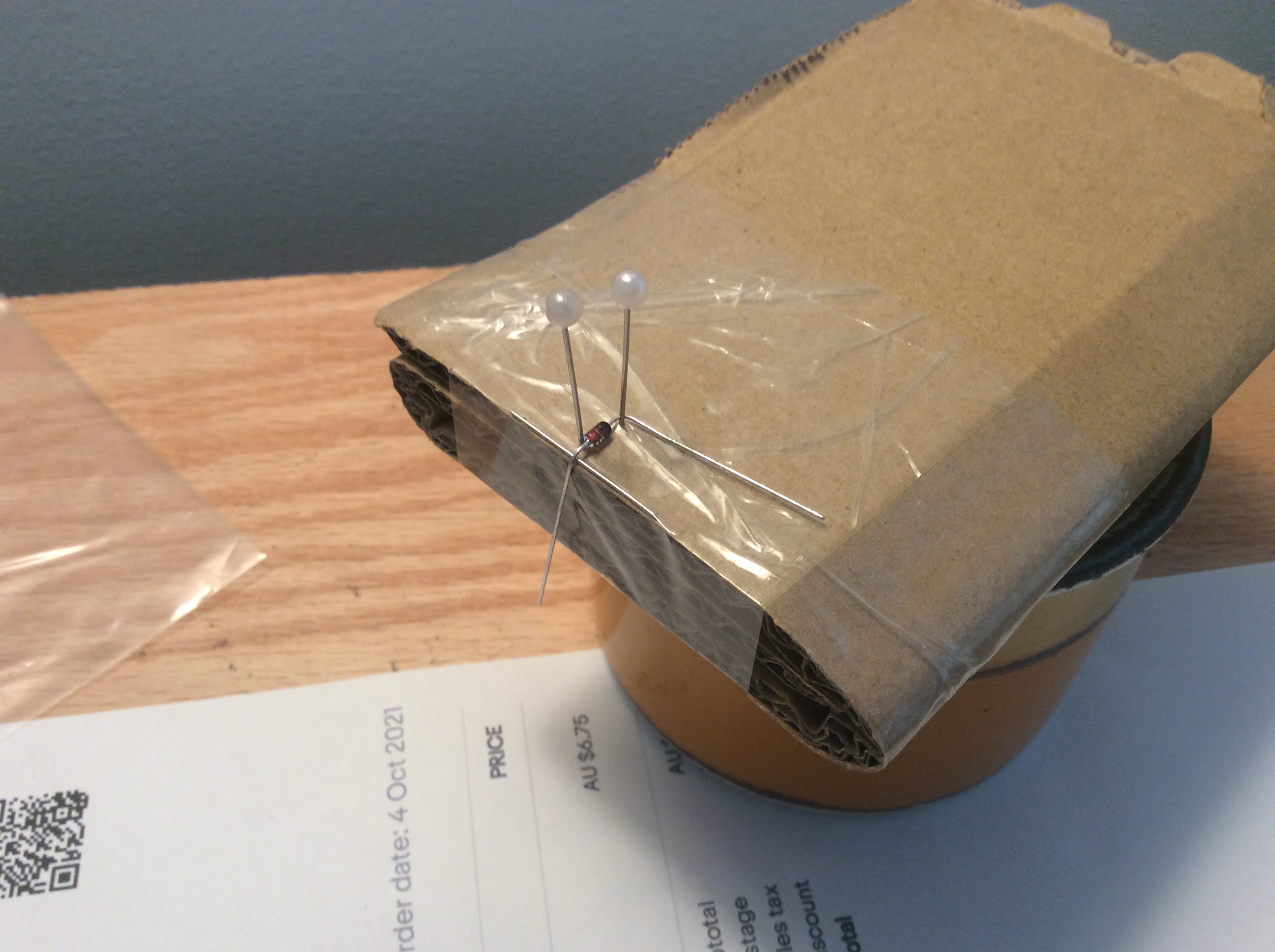
After settling into the new place, and buying a desk to work on, I ordered the diodes (1N4148) and patiently waited until I could get back into it.
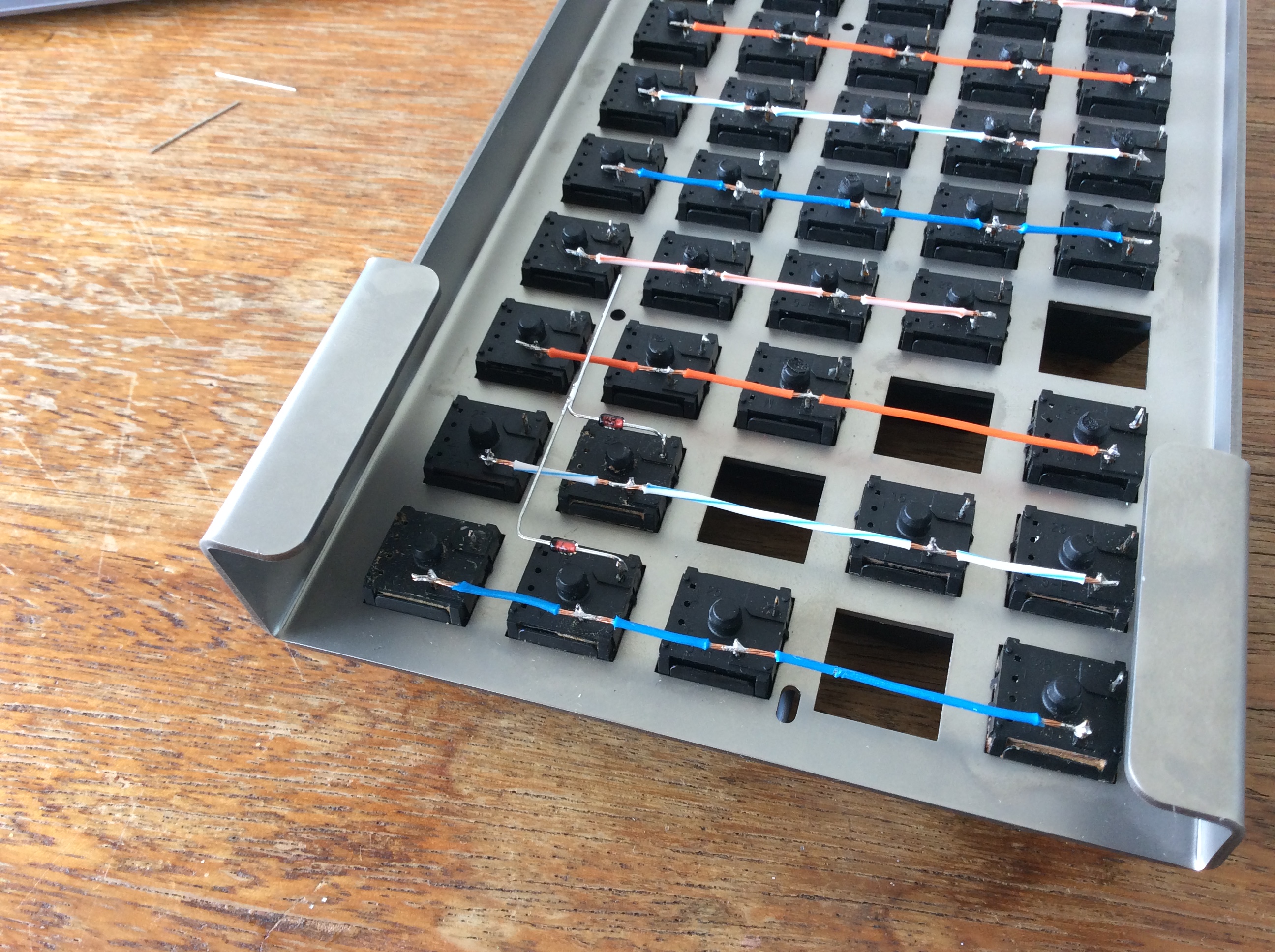
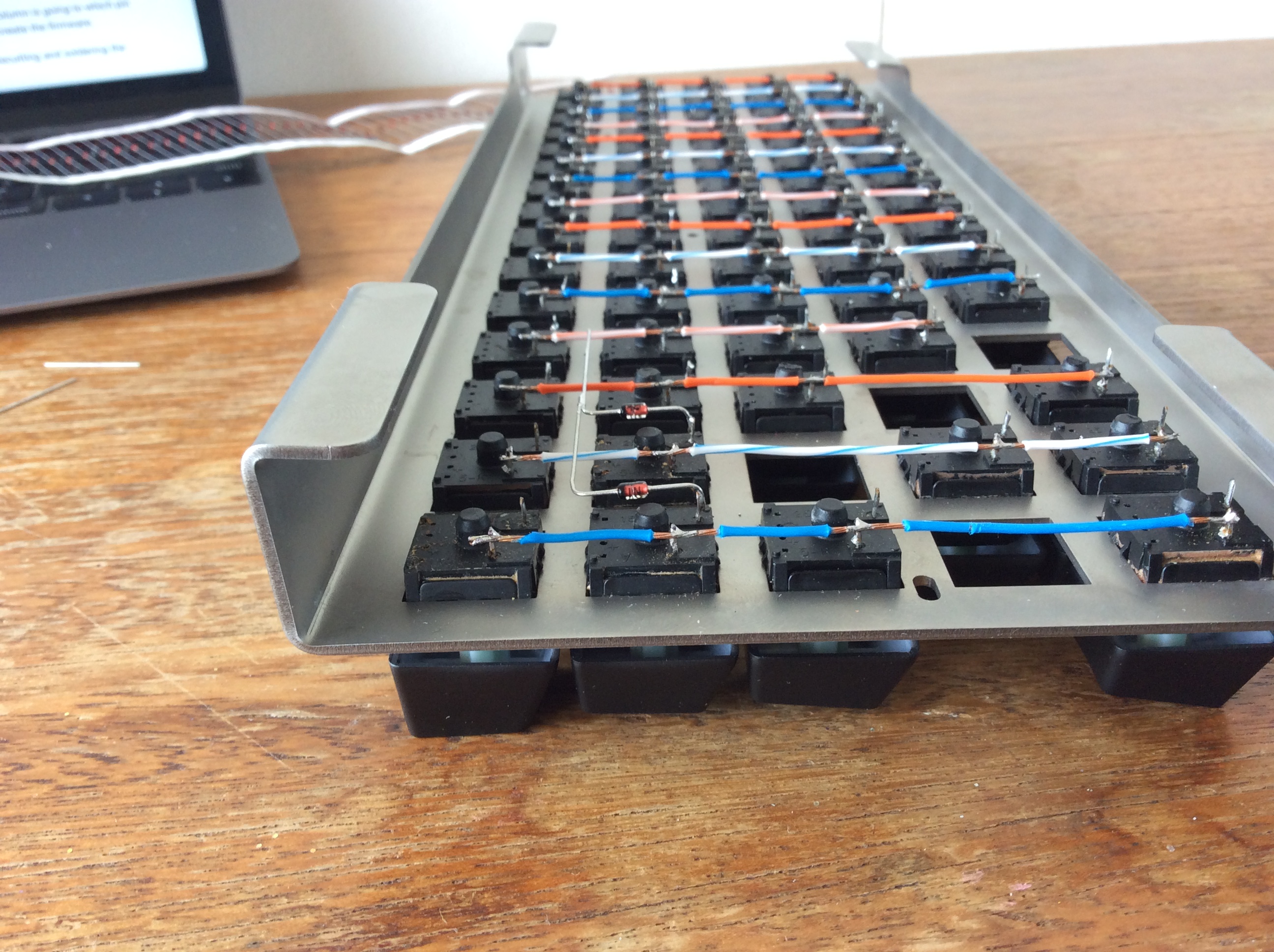
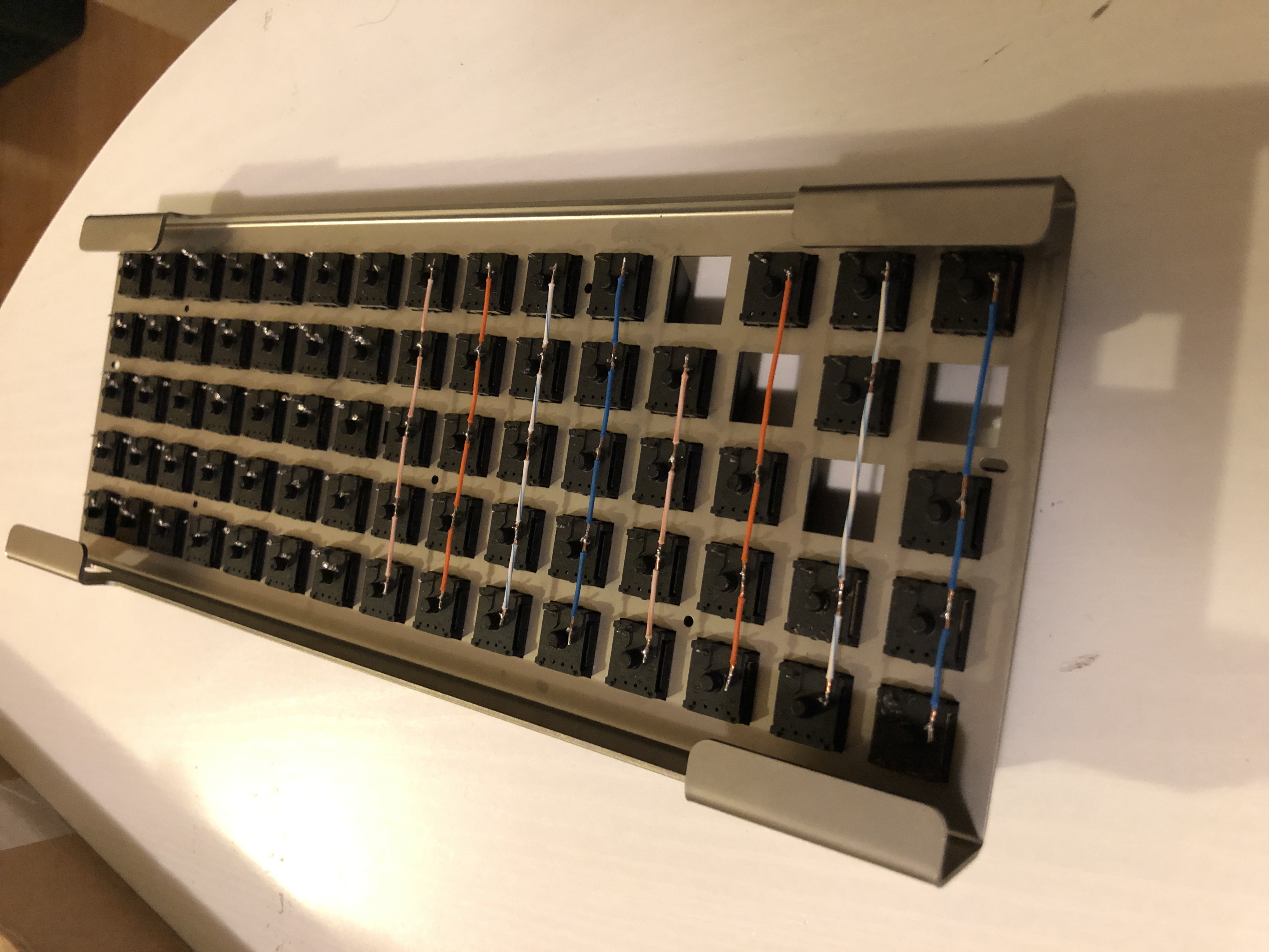
I took the approach of bending the diode legs at 90 degrees on either side and soldering them to the switch and the next diode in line. This looked good when it was just a couple of diodes, but when I got a whole row done it started looking sloppy. I attributed this to eye-balling the bend locations. Also, the point at which each diode joined the next looked bad, maybe because the parallel solder joints have to be perfect to look right. It's also very hard to make each joint the same length and same angle etc. even if the bend locations were measured.
The GF claimed the new desk, so I had to make do (I actually love my home made desk).
I decided that there was no point in doing every row the same way when I wasn't happy with how it turned out; so I made a jig for the remaining rows.
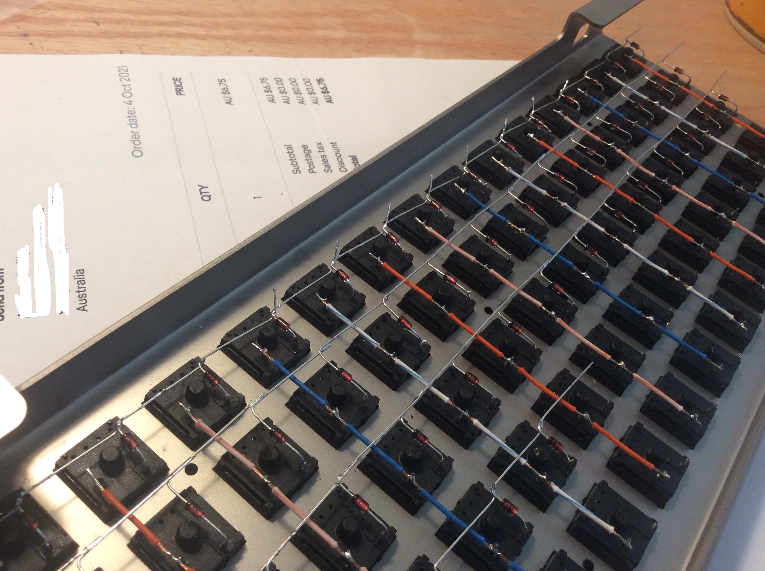
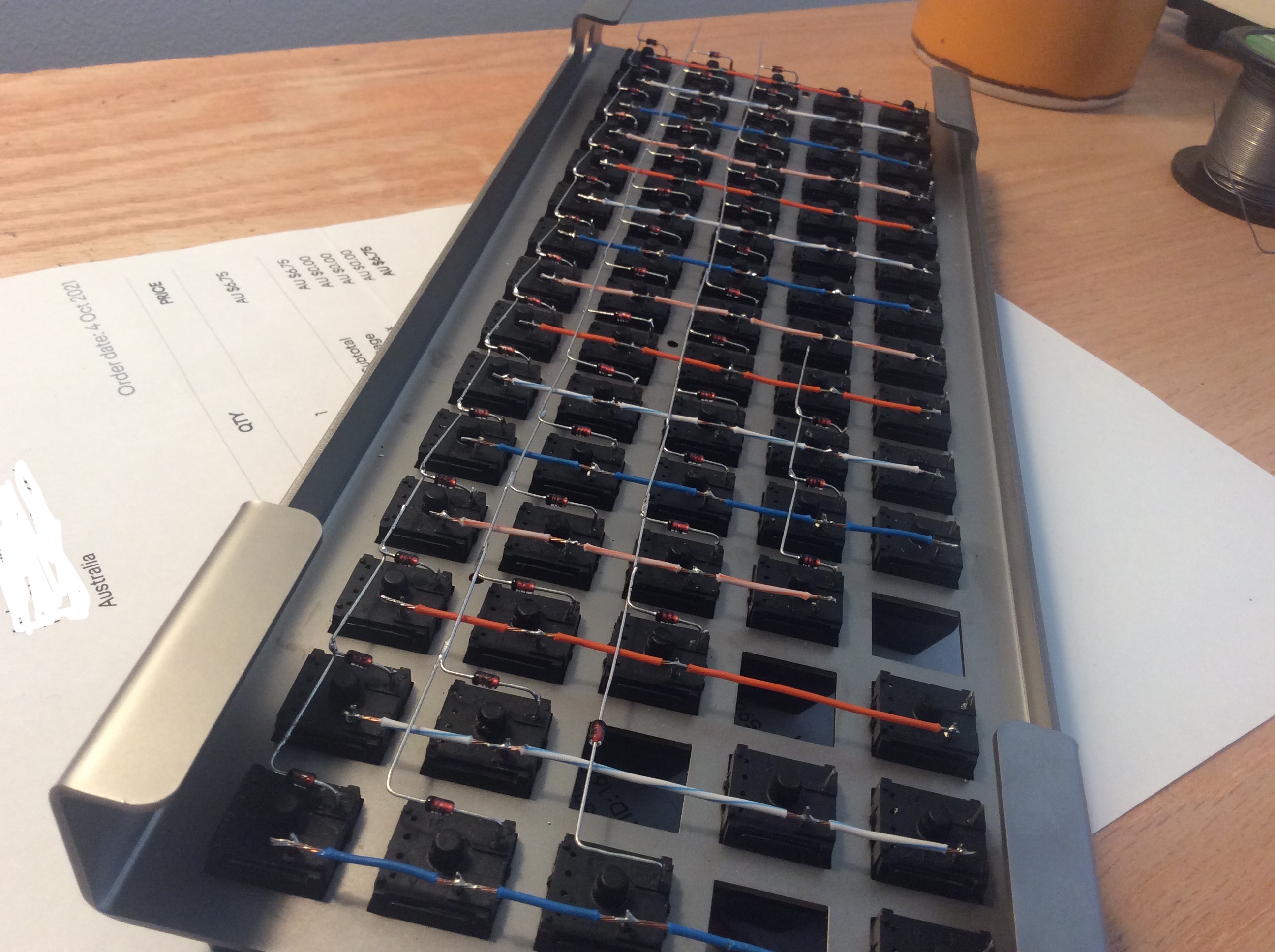
Once I soldered a few in place it seemed logical to weave the diode leg around the next diode leg to hold it in place, this also made a much more consistent joint, visually.
I did the remaining rows in this fashion and was really happy with how they turned out.
In fact they turned out so well, that I went back and redid the other two rows the same way!
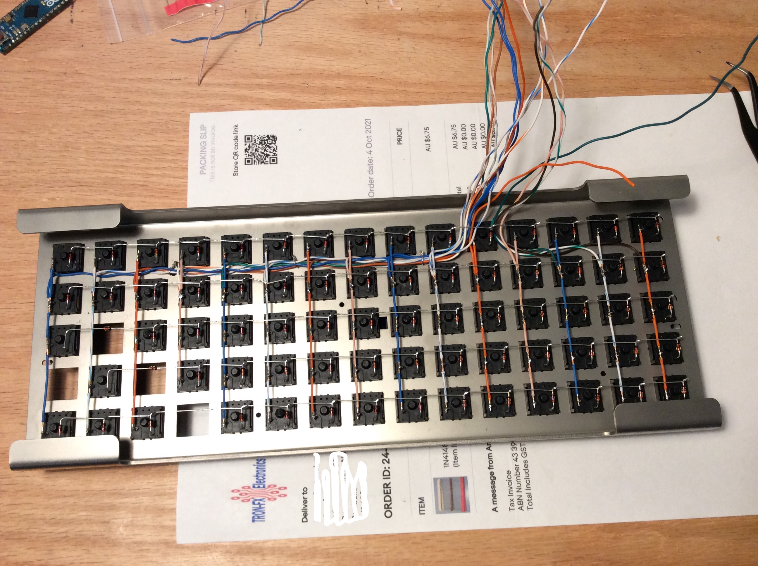
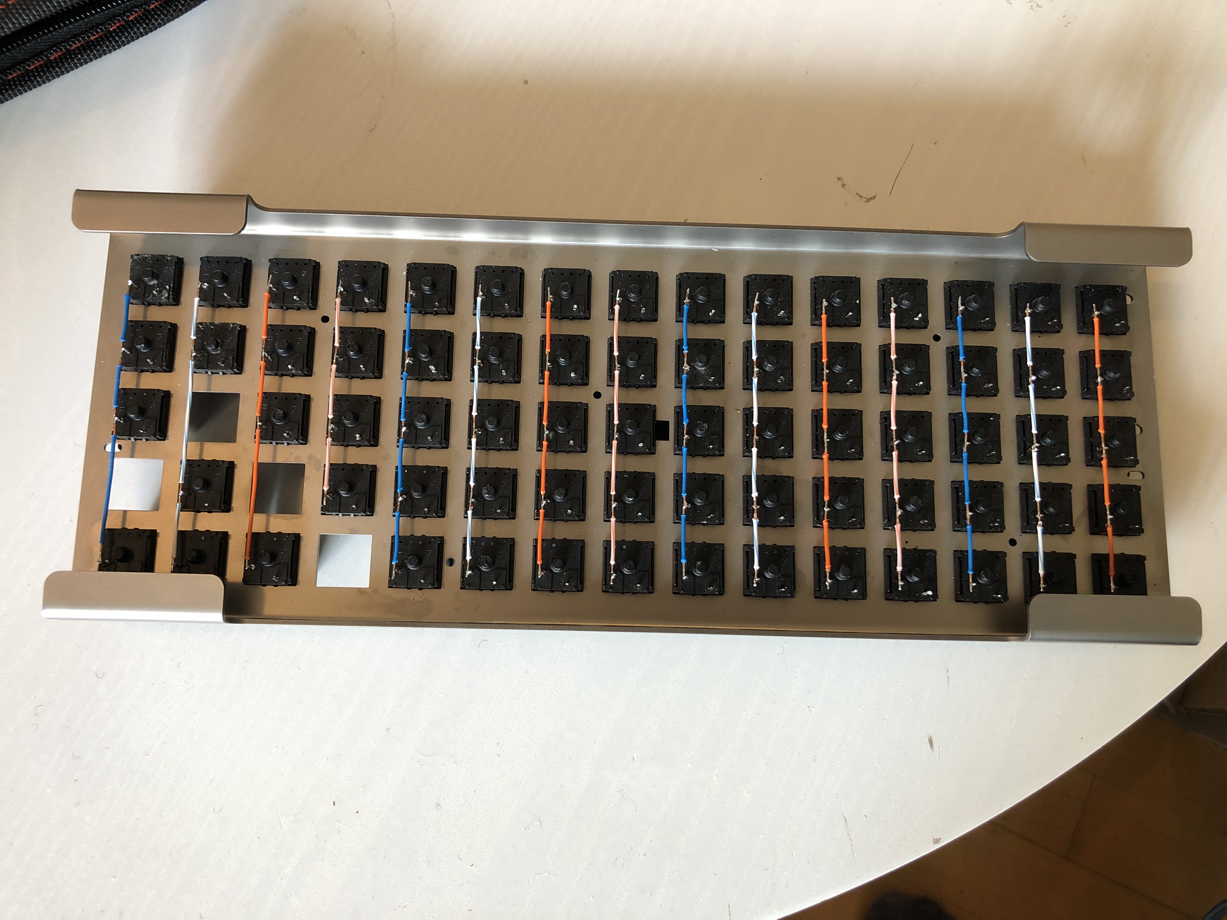
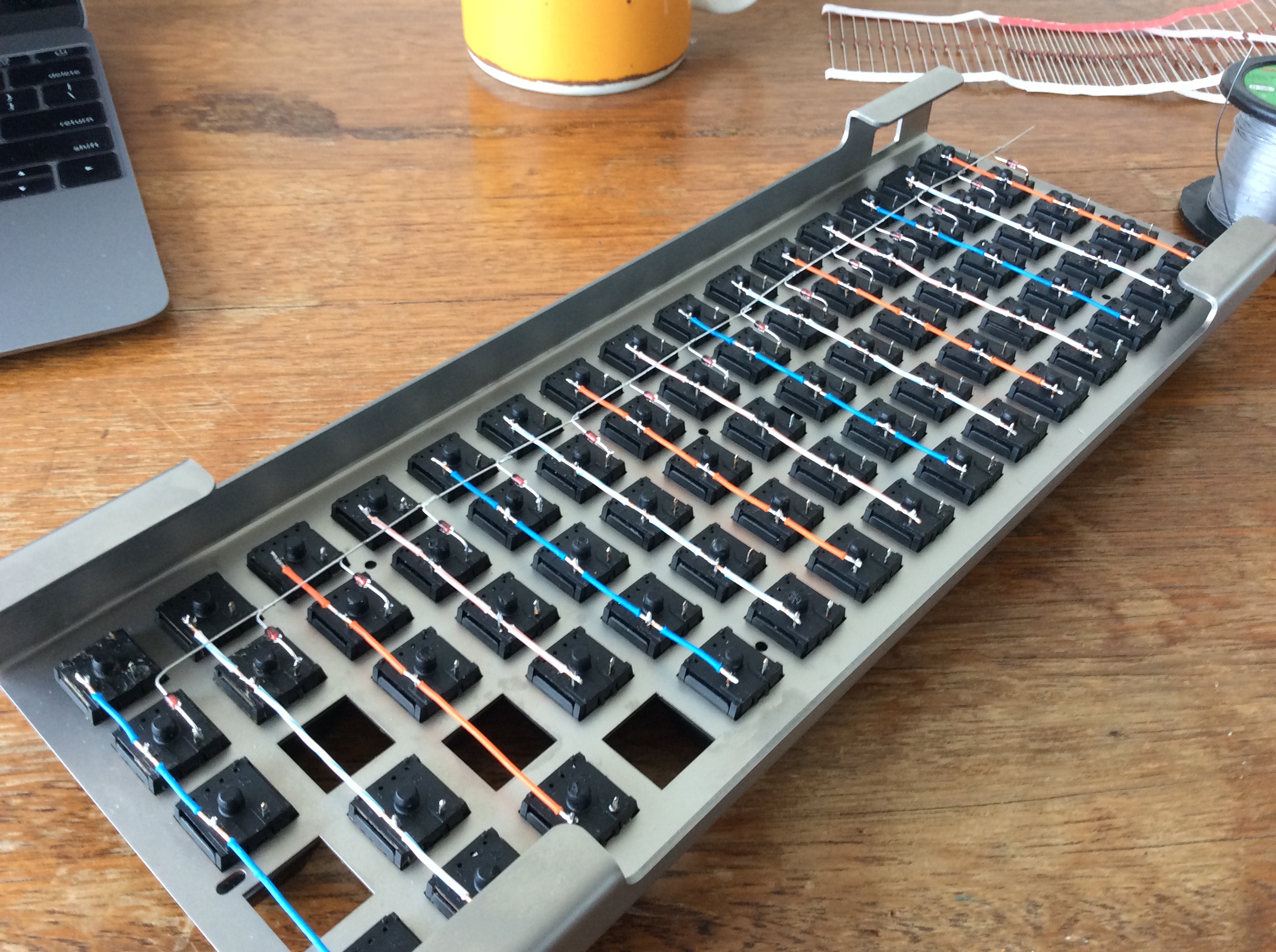
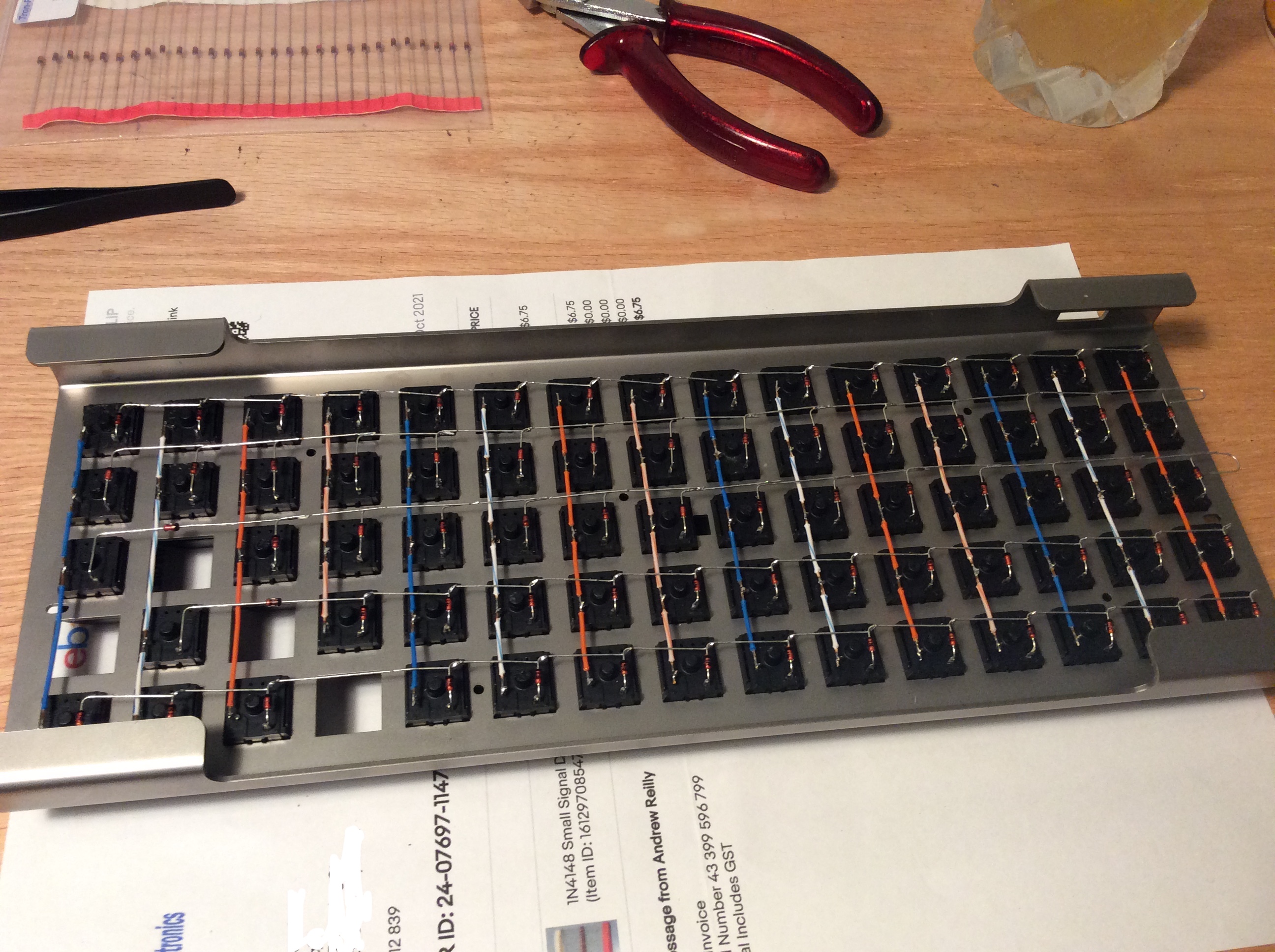
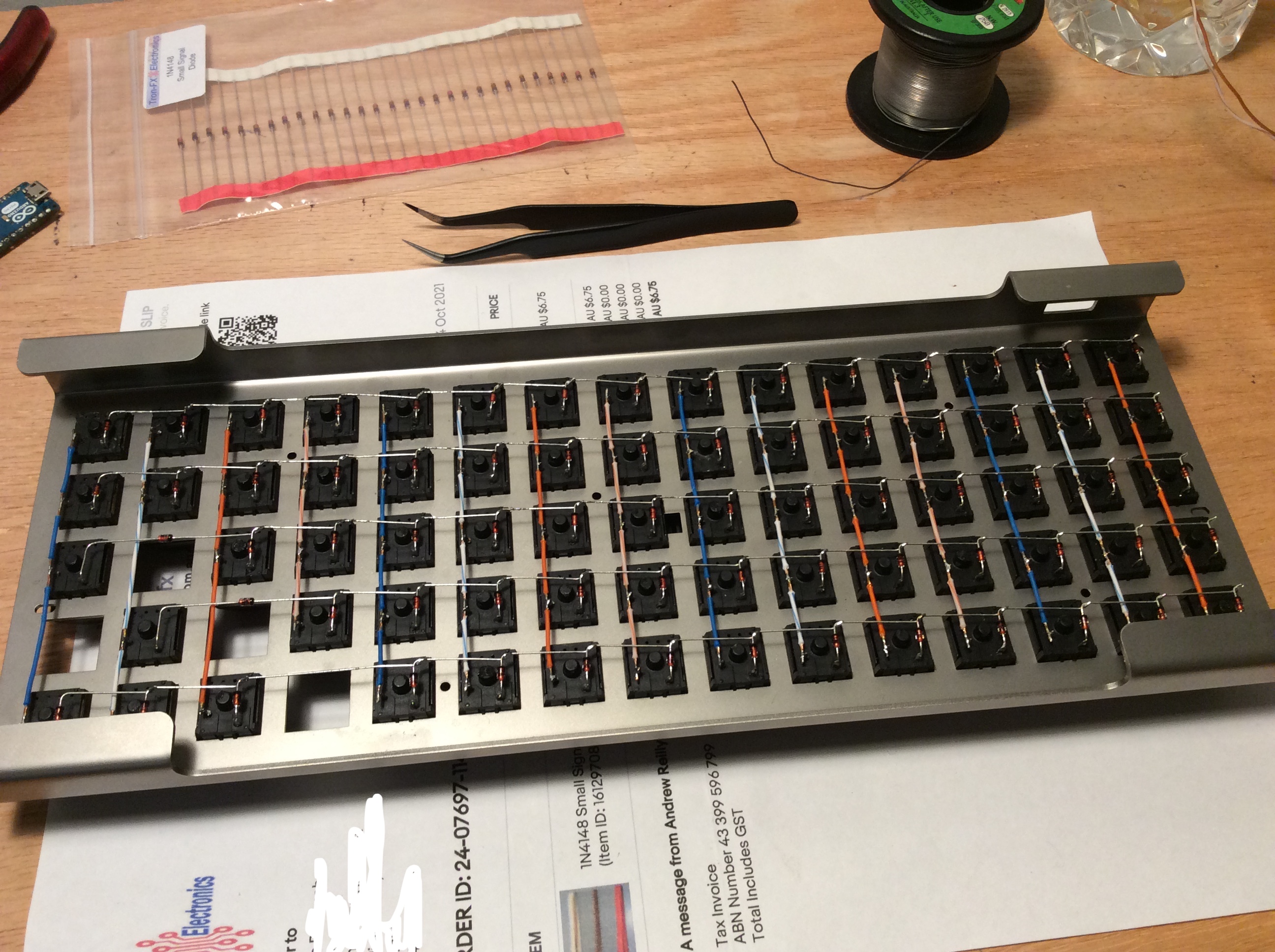
Added the micro controller wires for the columns. I used some off cut diode legs to tie the cables together at pionts, to keep things neat.
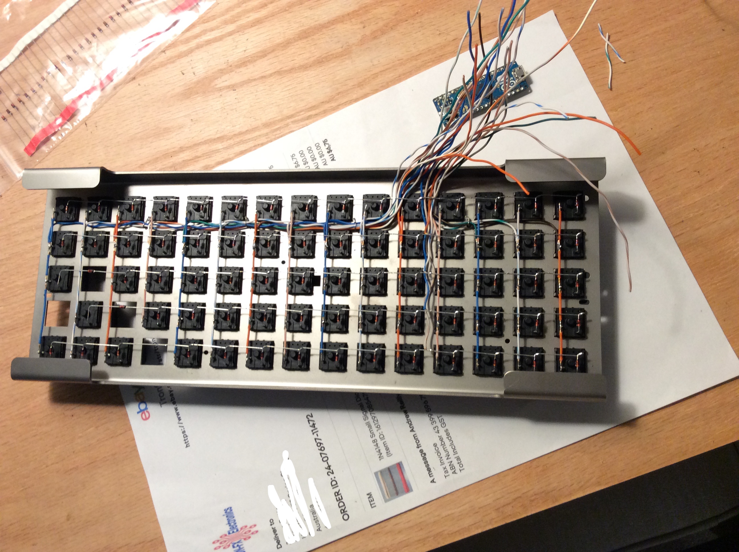
Row wires next.
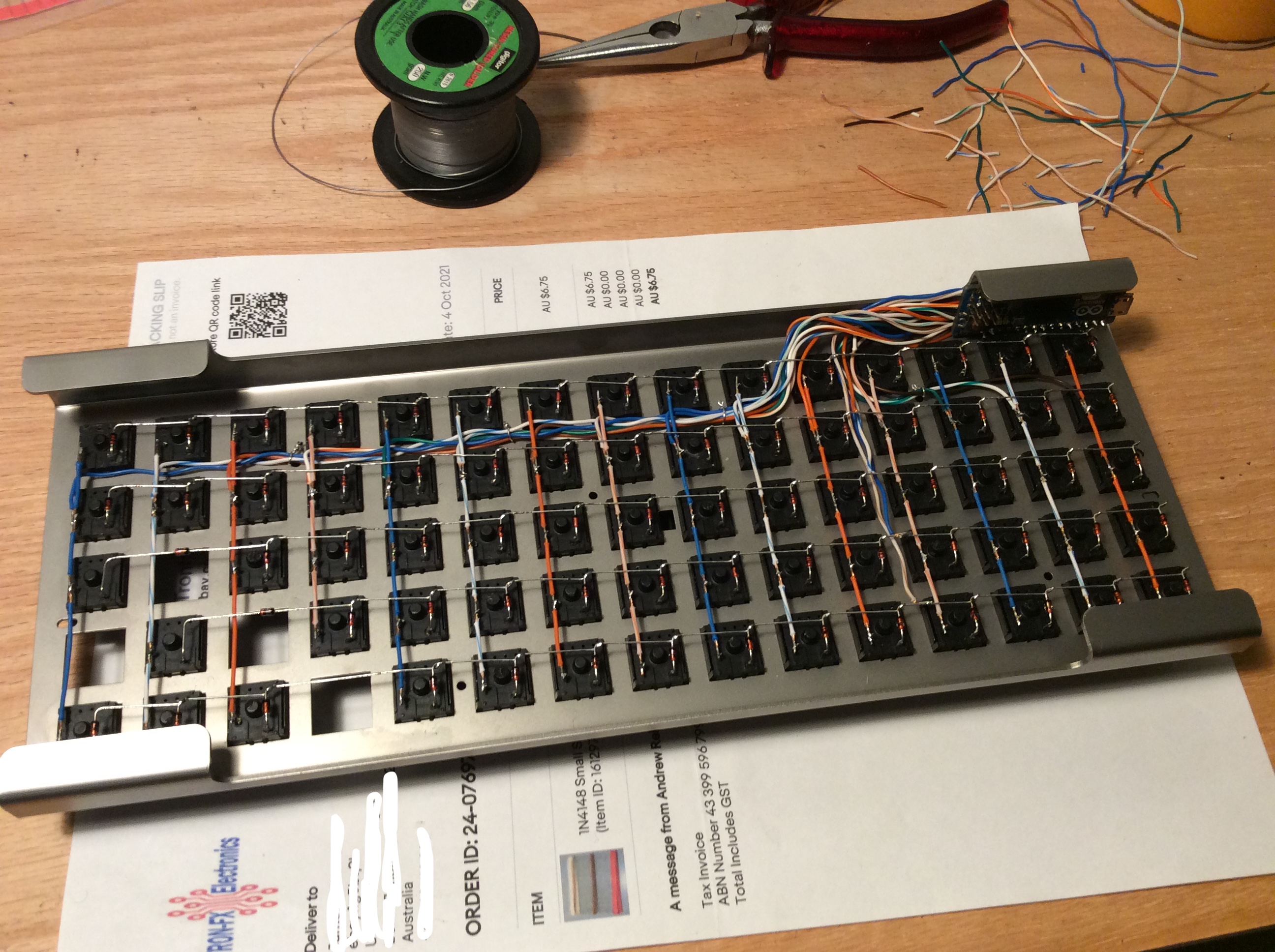
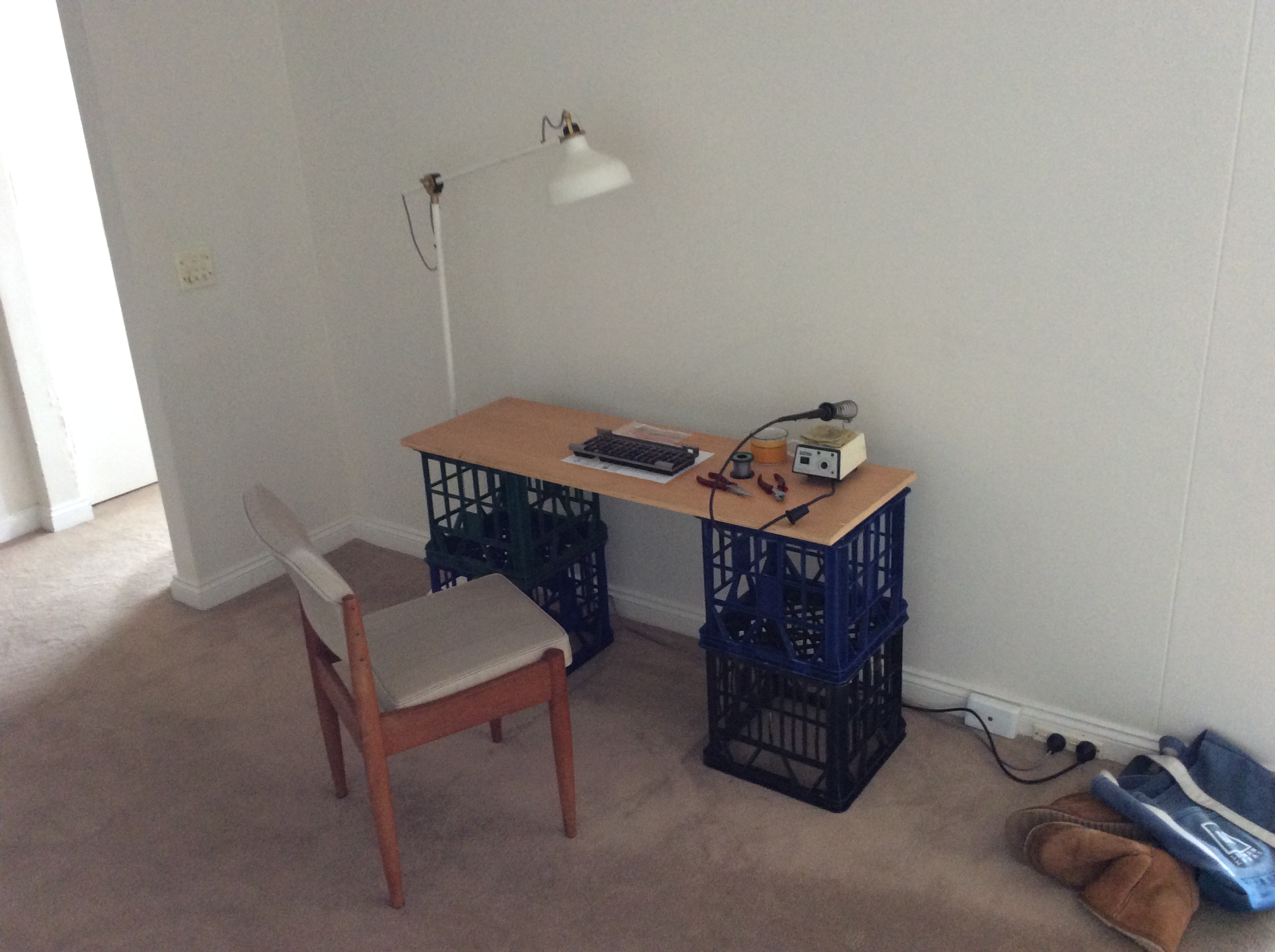
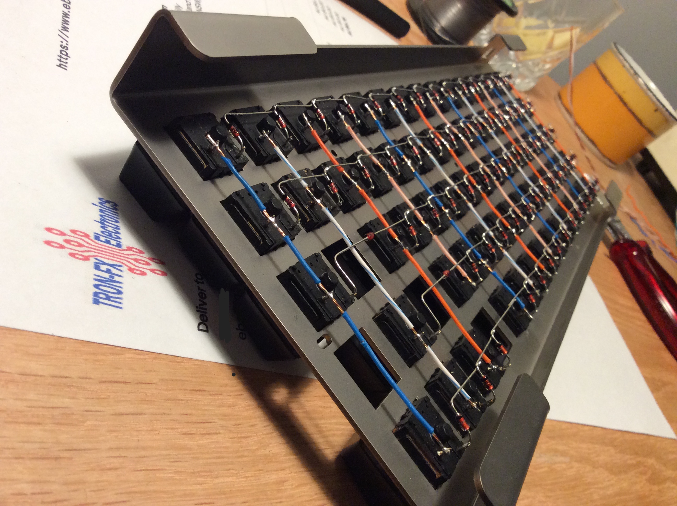
Trial fitted the micro controller.
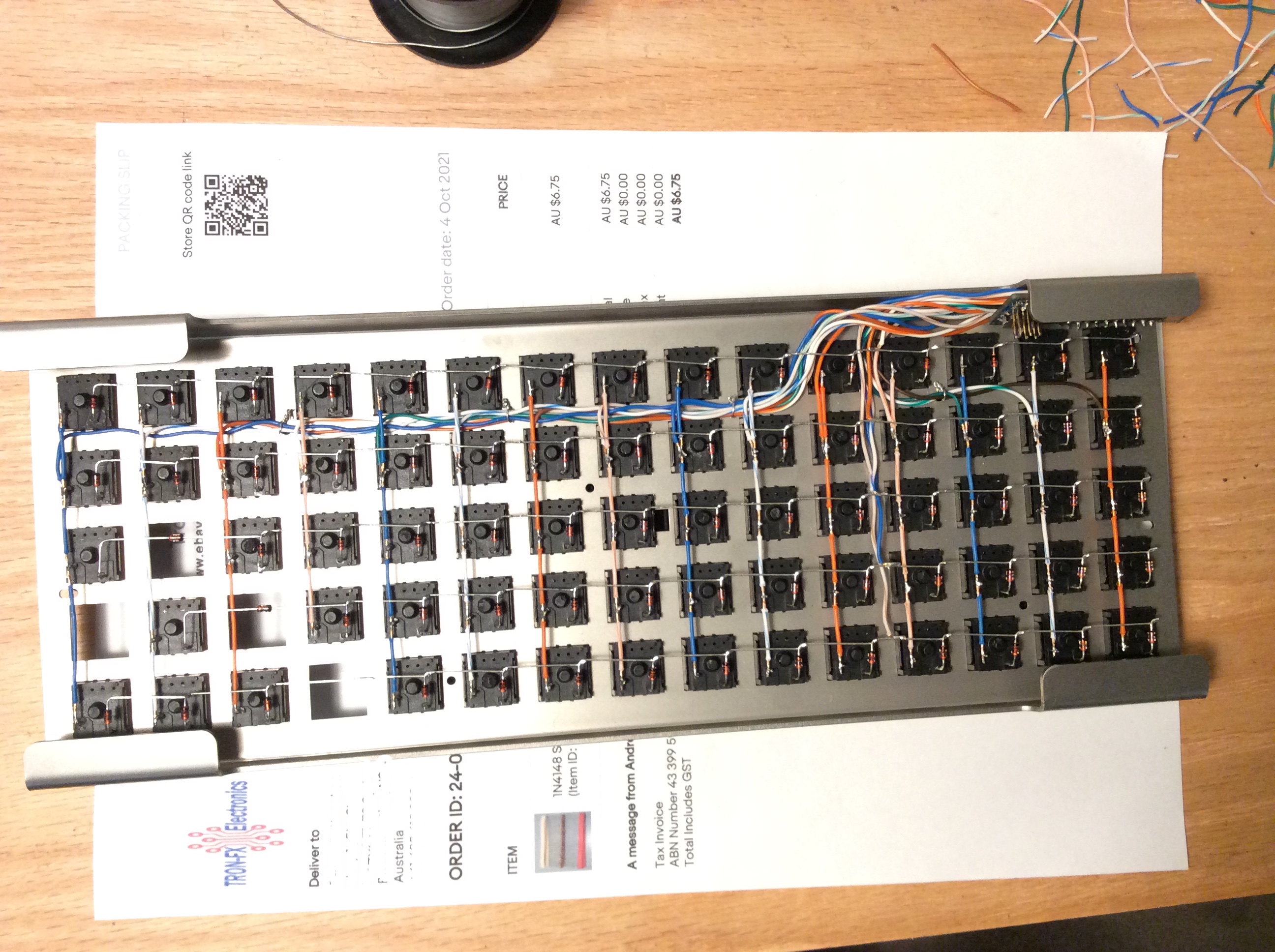
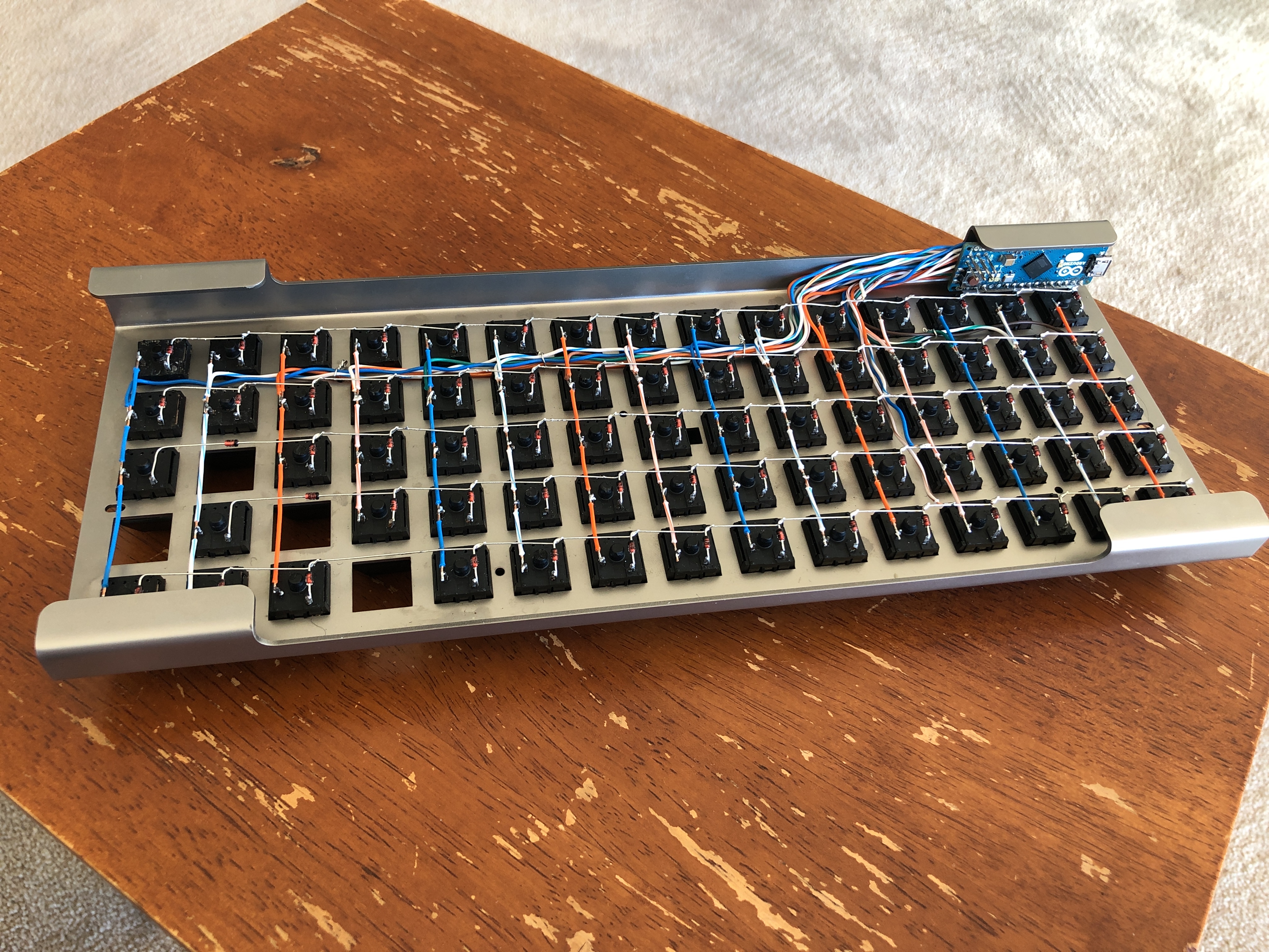
Rotated the micro controller to untwist the wires, this is the final fitment. I managed to use a couple of pieces of cable tie to jam the micro controller in the keyboard foot. It works surprisingly well, really solid.
It was now time to flash the micro controller and test the board!
The first mistake I made at this stage was to assume that, because the links on the QMK website weren't working, they had been supersceded. I went off on a tangent of trying to work out how to use the keyboard files included with QMK Toolbox on my keyboard. Modifying the config files seemed doable but I couldn't understand that I wasn't able to easily find a vanilla firmware to work from. At this stage I tried to find the sites prescribed by QMK on Google, and lo and behold, they still existed.
The sites you need are http://www.keyboard-layout-editor.com/ (note HTTP, no S) and https://kbfirmware.com/. The first site is to layout your keyboard, the second to create the firmware. I found it easiest to simply place the keys on keyboard-layout-editor and then do everything else on kbfirmware. To transfer your layout from the former to the latter, you need to copy the data in the "raw output" tab on keyboard-layout-editor and paste in the box on kbfirmware.
Having worked this out (it's very straight forward if you use the above sites straight up) I quickly found out that the pinout diagram I used for the Arduino I had was wrong, so some of the columns and rows were swapped or had the wrong pins assigned in the firmware. This was a fairly simple fix, just changed the pin allocations on kbfirmware and reflashed.
This revealed another issue. The micro controller that had been buried in my cupboard, and was originally a hand me down, had two dead pins. This was causing two rows on the keyboard not to register. I thought this meant that I'd have to replace the micro, which was a bit of a downer, but rechecking the pinout revealed that there were more available pins on the Leonardo. I adjusted the length of the two suspect row wires and soldered them to the new input pins, updated the firmware configuration and voila, keyboard worked!
From here there was no more electrical work required, just defining and tweaking the key map.
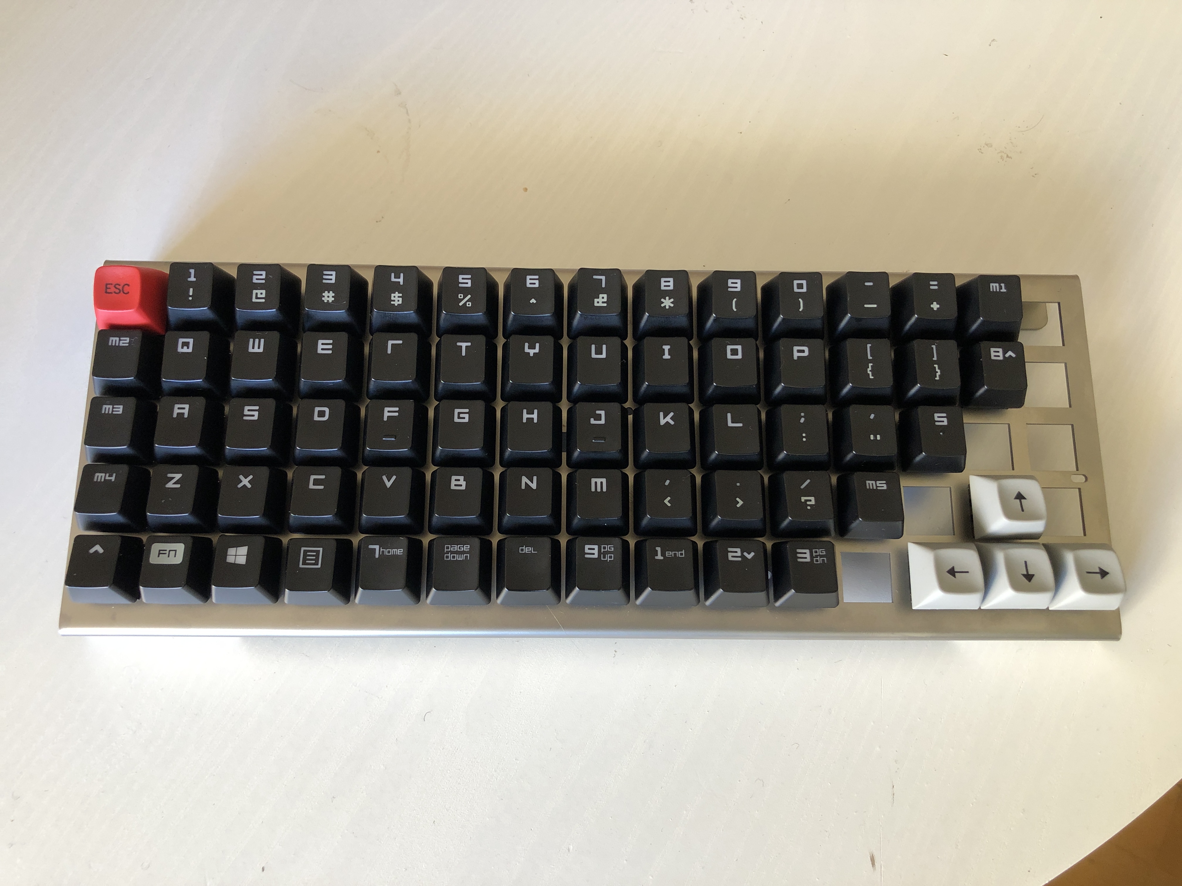
Once I started learning the keyboard I found that the four space bar keys having random symbols on them was quite distracting. My solution was to paint the four key tops white. This solved the problem but looked quite harsh. I was using nail polish for this and another colour option was yellow, very similar to the colour of my Lotus, so I felt I had to at least give it a try. I'm pretty happy with how it turned out!
Since then I have had issues with the Tab key not registering, and with some of the other keys not being clicky. The solution in both cases has just been to swap in some spare switches, which is super easy when all the wiring is in place.
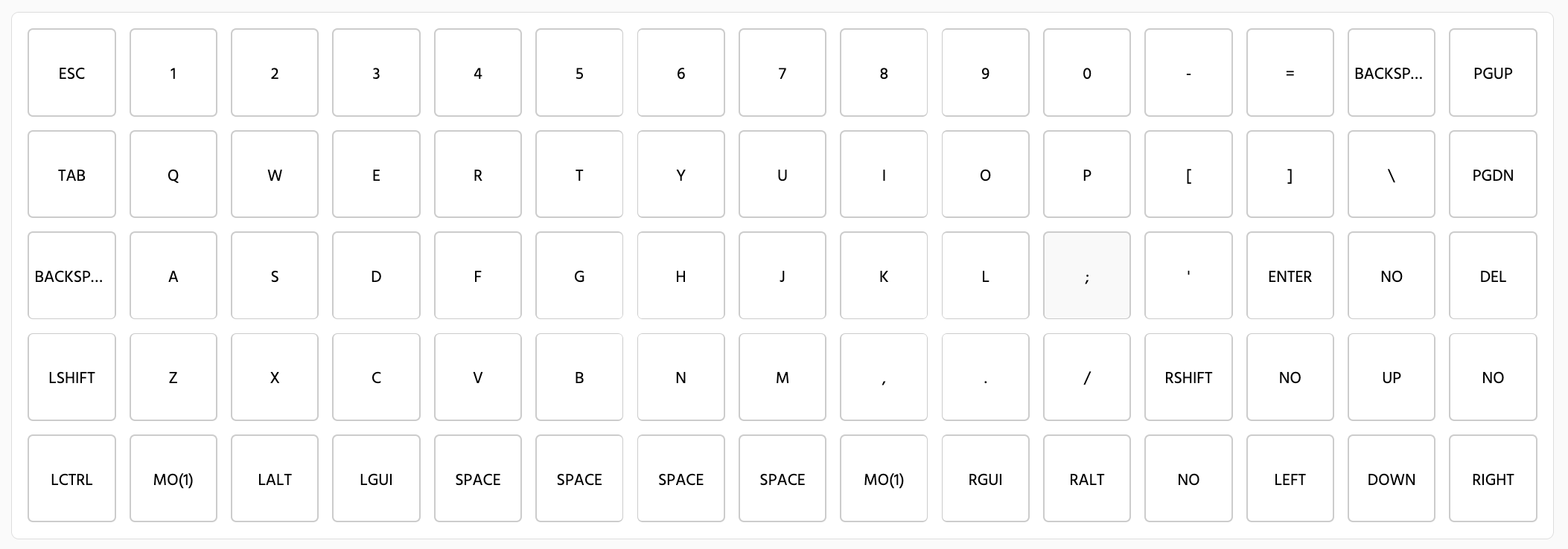
My layer 0 map
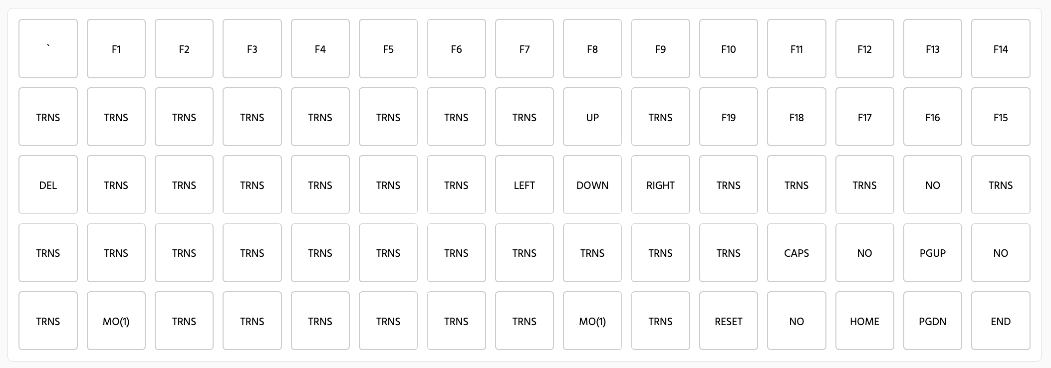
Layer 1 map
All up I'm super happy with how the keyboard ended up. The fact that it took time and I had to develop skills to build it just added to the experience. It took around a month from first purchase to having it finished but there was planning time before hand and some tuning of the maps afterwards. One of the things I don't like about buying new is that the whole experience is over so fast, getting a month and a half of anticipation and creation out of a purchase is brilliant.
If you're someone that just wants a cheap ortho keyboard, I can't recommend doing this. The time you sink into it outweighs any cost savings, not to mention that most people probably won't like the aesthetic. If you're trying to decide whether it's worth forking out for an ortho, in my opinion it is. The layout, and being able to customise your maps justifies paying a premium to get the one that you like. I must say though, that from a purely functional perspective, the bent stainless frame combined with the Razer green switches is really nice. Very solid, nice tactile feeling, great sound, and I haven't had a key bounce or not register at all, except where there was an actual fault with a switch.
I think the 75 key layout was a good choice. Having used it for around two weeks so far, I'm pretty sure that I would have been annoyed having to learn the maps for a smaller board like the Preonic, not to mention the Plank. I have all but stopped using the two right most columns but that is still one more column than a Preonic/Plank. The ortho layout made me instantly convert to caps for backspace (I couldn't make the change on staggered), as the old backspace location has changed a fair bit and I kept missing it. The only key I'm not certain about at the moment is del. I have it set as fn+backspace (the old caps key) but it isn't gelling for me. I might end up making it the right hand space key. I like having the arrow keys and pg up/down as separate keys where they are too, keying around with a coffee or something is nice with them.