I've never read any vehicle dynamics books due to a fear that the overly technical nature of them will lessen my enjoyment of the subject. I have studied dynamics in general however, and most of my ideas stem from that. I'm sure my concepts aren't new, and if they are it probably means they're wrong. This is entirely possible but I enjoy considering the subject and the concepts I use seem to explain my experience of the real world well.
The intention of this post is to explain the effects of the weight distribution of a vehicle and to show how this attribute alone isn't enough to classify a vehicle's dynamics. I'll start by covering some basic concepts then combine them to explain the effect in an actual car. At the end I'll try to tie weight distribution in with FWD/RWD to show that these too, aren't enough to classify a vehicle's dynamics.
My assumptions for this post are that the vehicle is a conventional 2WD car with a relatively heavy engine/gearbox. Most cars on the road are like this, currently. Also, cornering is the main consideration in this article. Weight distribution does effect the straight line performance of a car but these effects are easier to understand so I won't go into them here.
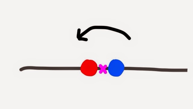
Firstly I'll look at Rotational inertia. Imagine you have a straight rod and two masses (red and blue circles) that you can easily fix to this rod. If you place the masses midway along the rod and then try to spin the rod around it's halfway point (pink cross). You will find that it isn't too difficult.
Now if you move the weights one to either end of the rod and again try to spin it around its halfway point it will be much more difficult.
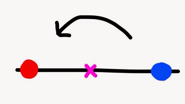
This is rotational inertia. Keeping weight near the point around which you want to rotate ensures there is a minimum resistance to the rotation.
The engine placement in a car is normally one of four possible locations. Front engine has the centre of mass of the engine in line with the front axle or forward of it. Front mid engine has the centre of mass of the engine in line with the front axle or rear of it. Rear mid engine has the engine in line with the rear axle or forward of it and rear engine is when the engine is in line with or behind the rear axle. Typical examples of these four configurations are given below, the cars in the images are oriented front to the left.
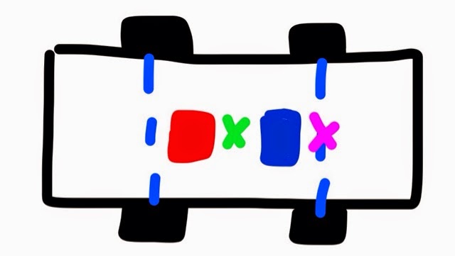
When a car is cornering its centre of rotation (the point the car rotates around when viewed from above) essentially moves between two places. The first is halfway between the rear wheels (pink cross) and the second is in the middle of the four wheels (green cross).
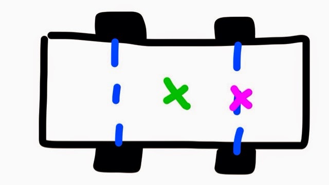
At turn in (transitioning from straight line to cornering) the car starts rotating around the rearmost point (pink cross). Once the car settles into cornering it rotates around the centre point (green cross).
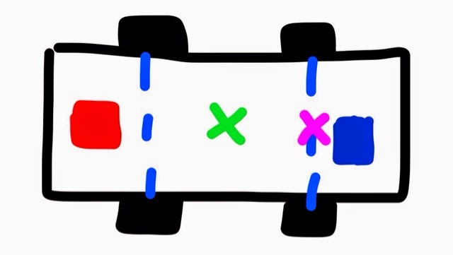
So now, by combining the concepts above, it will hopefully create an understanding of the effects of the location of weight within a car. We'll start by considering the rod with the two masses again. If we imagine that the rod is the chassis and most of the other, fairly evenly distributed, parts of the car and that one mass is the engine/gearbox, the other represents components that can be located fairly freely by engineers (passengers, fuel tank, battery etc.). We'll assume that the two masses are of equal weight and we will make our car have a 50:50 weight distribution (often claimed to be ideal).
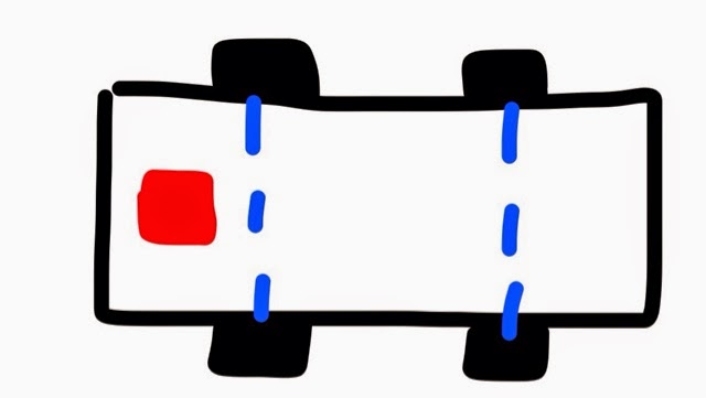
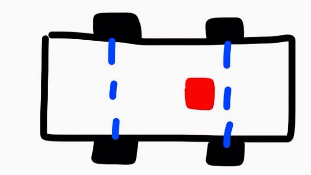
If we configure the car with the engine at the front, to keep the even weight distribution, the other mass will be right at the back (red and blue boxes in figure 8). When we consider this car during a corner the centre of rotation, once established in the corner, is in the middle of the car (green cross). This is the same configuration as mentioned with the rod when it was difficult to rotate I.e it is more difficult to get a front engined car to rotate (corner).
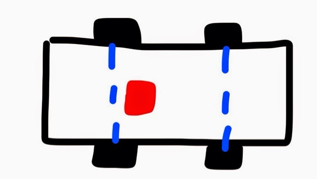
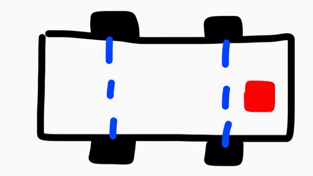
Moving the engine back behind the front axle means the other mass moves forward in front of the rear axle, as in the rod example that was easy to rotate I.e mid engined cars are easier to make rotate (Figure 9).
As originally stated, both of the above engine placements result in a 50:50 weight distribution however, both cars are not equal.
The other situation to consider is turn in. If we take the front engine example (Figure 8) and look at what happens when you try and rotate it around the pink cross it can be seen that although part of the weight is near the rotation point (blue box) the other part (red box/engine) is very far away i.e. Front engine cars are harder to turn in. If the configuration in Figure 9 is considered instead, the blue box is the same distance away from the point of rotation so contributes the same resistance to turn in however, the engine (red box) is now closer to the rotation point i.e. Mid engine cars are easier to turn in.
One thing to remember with inertia is that it's only an issue when you're trying to enter or exit a corner or if you're trying to change your line. Once established in a steady corner the weight distribution doesn't have an effect (See notes section). So if the cars are equivalent mid corner and the mid engine layout is superior elsewhere, then the mid engine layout is superior. It can also be seen from Figure 9 that if you had to place all your weight in one place, placing it where the blue box is is the best compromise. This explains why mid rear engine placement is popular in lightweight performance cars where the engine/gearbox make up for a larger percentage of the vehicle weight.
Further notes on weight distribution. (Section under construction) Driven wheels are a secondary effect. Weight and traction. Note on Front engine controllability in drift and rear engine superior turn in.